


Keyestudio Temel Başlangıç Öğrenme Kiti - Arduino Eğitim Projesi İçin
Keyestudio Temel Başlangıç Öğrenme Kiti - Arduino Eğitim Projesi İçin
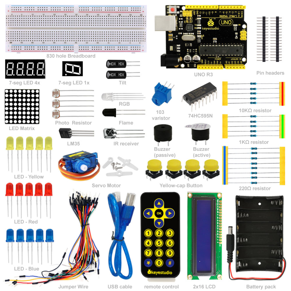
Kit Tanıtımı
Bu, Arduino ile ilgilenen yeni başlayanlar için özel olarak hazırlanan temel Başlangıç Setidir. Arduino'nun en yaygın ve kullanışlı elektronik bileşenlerine sahip olacaksınız. Dahası, size proje tanıtımı ve kaynak kodları dahil olmak üzere ayrıntılı bir öğretici sunuyoruz. Bu temel projeleri kullanarak Arduino hakkında bilgi edinebilirsiniz. Bu kit, fiziksel dünyayı sensörler ile kontrol etmenize yardımcı olacak
2. Kit İçeriği
| Adet x Parça | ||
|---|---|---|
| 1 x keyestudio UNO R3 Denetleyici | ||
| 5 x LED - Mavi | ||
| 5 x LED - Kırmızı | ||
| 5 x LED - Sarı | ||
| 1 x LED - RGB | ||
| 5 x 10K Ohm Direnç | ||
| 5 x 1K Ohm Direnç | ||
| 8 x 220 Ohm Direnç | ||
| 1 x 10K Ohm Direnç | ||
| 1 x 7-seg LED 1x modül | ||
| 1 x 7-seg LED 4x modül | ||
| 1 x 8x8 dot LED Düzeni | ||
| 1 x Buzzer (aktif) | ||
| 1 x Buzzer (pasif) | ||
| 1 x Alev sensör | ||
| 1 x IR Alıcı | ||
| 1 x IR Uzaktan Kumanda | ||
| 1 x LM35 Sıcaklık Sensörü | ||
| 2 x Ball Eğim sensörü | ||
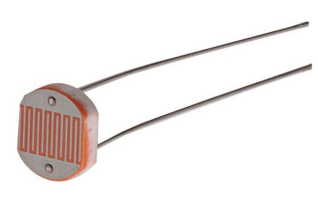
| 3 x Fotorezistör | ||
| 4 x Küçük buton anahtar | ||
| 1 x IC 74HC595N 16-pin DIP | ||
| 1 x LCD 1602 | ||
| 1 x 9g servo | ||
| 1 x 830-pin Breadboard | ||
| Dupont Bağlantı Kablosu | ||
| 1 x 6 hücre AA Pil Yatağı | ||
| 1 x USB Kablo |
3. Proje Listesi
- 1. Hello World / Merhaba Dünya
- 2. LED Blinking / Yanıp Sönen LED
- 3. PWM / PWM
- 4. Traffic Light / Trafik Işığı
- 5. LED Chasing Effect / LED Takip Efekti
- 6. Button-controlled LED / Buton Kontrollü LED
- 7. Active Buzzer / Aktif Buzzer
- 8. Passive Buzzer / Pasif Buzzer
- 9. RGB LED / RGB LED
- 10. Photo Resistor / Fotorezistör
- 11. Flame Sensor / Alev Sensörü
- 12. LM35 Temperature Sensor / LM35 Sıcaklık Sensörü
- 13. Tilt Switch / Eğim Kontağı
- 14. IR Remote Control / IR Uzaktan Kumanda
- 15. Analog Value Reading / Analog Değer Okuma
- 16. 74HC595 / 74HC595 Yonga
- 17. 1-digit LED Segment Display / 1-basamak LED Segment gösterge
- 18. 4-digit LED Segment Display / 4-basamak LeED Segment gösterge
- 19. 8*8 LED Matrix / 8x8 LED Matriks
- 20. 1602 LCD / 1602 LCD
- 21. 9g Servo Control / 9g Servo Kontrol
4. Project Details / Proje Listesi
Project 1: Hello World / Merhaba Dünya
Introduction: / Tanıtım
As for starters, we will begin with something simple. In this project, you only need an Arduino and a USB cable to start the "Hello World!" experiment.This is not only a communication test of your Arduino and PC, but also a primer project for you to have your first try in the Arduino world!
Yeni başlayanlar için basit bir şeyle başlayacağız. Bu "Hello World!" (Merhaba Dünya) projesini başlatmak için sadece bir Arduino kart ve bir USB kablosuna ihtiyacınız var. deneme. Bu sadece Arduino ve PC'nizin (kişisel bilgisayarınızın) bir iletişim testi değil, aynı zamanda Arduino dünyasındaki ilk denemeniz için bir başlangıç projesidir!
Hardware Required: / Gerekli Donanım
1. Arduino board x1
2. USB cable x1
1. Arduino kart x1
2. USB kablosu x1
Sample Code: / Örnek Kod
After installing driver for Arduino, let's open Arduino software and compile the code that enables Arduino to print"Hello World!" under your instruction. Of course, you can compile the code for Arduino to continuously echo "Hello World!" without instruction. A simple If () statement will do the instruction trick. With the onboard LED connected to pin 13, you can instruct the LED to blink first when Arduino gets an instruction and then print the character"Hello World!”.
Arduino için sürücüyü kurduktan sonra, Arduino yazılımını açalım ve Arduino'nun "Hello World!" yazması için kodları girelim. Basit bir If () talimatı ile Arduino'nun sürekli ve aralıklı "Hello World!" yazmasını da sağlayabilirsiniz. Arduino bir talimat aldığında, Pin 13'e bağlı yerleşik LED'in, önce yanıp sönmesini, ardından "Merhaba Dünya!" yazdırmasını da sağlayabilirsiniz.
int val;//define variable val
int ledpin=13;// define digital interface 13
void setup()
{
Serial.begin(9600);// set the baud rate at 9600 to match the software set up. When connected to a specific device, (e.g. bluetooth), the baud rate needs to be the same with it.
pinMode(ledpin,OUTPUT);// initialize digital pin 13 as output. When using I/O ports on an Arduino, this kind of set up is always needed.
}
void loop()
{
val=Serial.read();// read the instruction or character from PC to Arduino, and assign them to Val.
if(val=='R')// determine if the instruction or character received is "R”.
{  // if it’s "R”,
digitalWrite(ledpin,HIGH);// set the LED on digital pin 13 on.
delay(500);
digitalWrite(ledpin,LOW);// set the LED on digital pin 13 off.
delay(500);
Serial.println("Hello World!");// display"Hello World!”string.
}
}
Result: / Sonuç
Click serial port monitor
Input R
LED 13 will blink once
PC will receive information from Arduino: Hello World!
Seri port monitörüne tıklayın
kutucuğa R yazın
LED 13 bir kez yanıp sönecektir
PC Arduino'dan bilgi alacaktır: Merhaba Dünya!
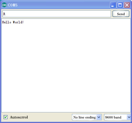
After choosing the right port, the experiment is very easy for you!
Doğru portu seçtiktiyseniz, deney sizin için çok kolaydır!
Project 2: LED Blinking / LED Yakıp Söndürme
Introduction: / Tanıtım
Blinking LED experiment is quite simple. In the "Hello World!" program, we have come across LED. This time, we are going to connect an LED to one of the digital pins rather than using LED13 which is soldered to the board. Apart from an Arduino and a USB cable, you will need extra parts as below:
Yanıp sönen LED deneyi oldukça basittir. "Merhaba Dünya!" programda LED ile tanıştık. Bu kez, karta lehimlenmiş LED13'ü kullanmak yerine dijital pinlerden birine LED bağlayacağız. Bir Arduino kart ve bir USB kablosunun yanı sıra, aşağıdaki gibi ekstra parçalara ihtiyacınız olacaktır:
Hardware Required:
1. Red M5 LED*1
2. 220? resistor*1
3. Breadboard*1
4. Breadboard jumper wires* several
1. Kırmızı M5 LED * 1
2. 220 Ohm direnç * 1
3. Breadboard * 1
4. Breadboard jumper kablo * birkaç adet
We follow below diagram from the experimental schematic link. Here we use digital pin 10. Connect an LED to a 220 ohm resistor to avoid high current damaging the LED.
Aşağıdaki şemayı takip edeceğiz. Burada dijital pin 10'u kullanıyoruz. Yüksek akımın LED'e zarar vermesini önlemek için LED'e 220 ohm bir direnç bağlayın.
Connection for UNO R3: / UNO R3 Bağantısı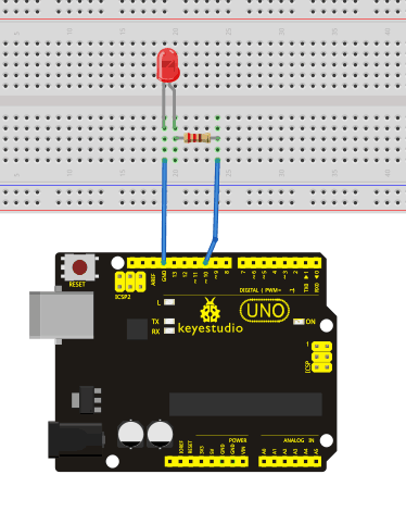
Sample Code: / Örnek Kod
int ledPin = 10; // define digital pin 10.
void setup()
{
pinMode(ledPin, OUTPUT);// define pin with LED connected as output.
}
void loop()
{
digitalWrite(ledPin, HIGH); // set the LED on.
delay(1000); // wait for a second.
digitalWrite(ledPin, LOW); // set the LED off.
delay(1000); // wait for a second
}
Result: / Sonuç
After downloading this program, in the experiment, you will see the LED connected to pin 10 turning on and off, with an interval approximately one second. The blinking LED experiment is now completed.
Kodu yükledikten sonra, deneyde, pin 10'a bağlı LED'in yaklaşık bir saniye aralıklarla yanıp söndüğünü göreceksiniz. Yanıp sönen LED deneyi şimdilik tamamlanmıştır.
Project 3: PWM / PWM
Introduction: / Tanıtım
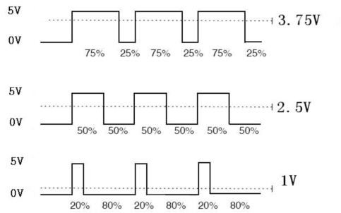
PWM, short for Pulse Width Modulation, is a technique used to encode analog signal level into digital ones. A computer cannot output analog voltage but only digital voltage values such as 0V or 5V. So we use a high resolution counter to encode a specific analog signal level by modulating the duty cycle of PMW. The PWM signal is also digitalized because in any given moment, fully on DC power supply is either 5V (ON), or 0V (OFF). The voltage or current is fed to the analog load (the device that uses the power) by repeated pulse sequence being ON or OFF. Being on, the current is fed to the load; being off, it's not. With adequate bandwidth, any analog value can be encoded using PWM. The output voltage value is calculated via the on and off time.
Output voltage = (turn on time/pulse time) * maximum voltage value
Sinyal Genişliği Modülasyonunun ingilizce kısaltması olan PWM, analog sinyal seviyesini dijital olanlara kodlamak için kullanılan bir tekniktir. Bir bilgisayar analog voltaj veremez, ancak yalnızca 0V veya 5V gibi dijital voltaj değerlerini verir. Bu nedenle, PMW'nin görev döngüsünü değiştirerek belirli bir analog sinyal seviyesini kodlamak için yüksek çözünürlüklü bir sayaç kullanıyoruz. PWM sinyali de dijitalleştirilmiştir, çünkü herhangi bir anda, DC güç kaynağında ya 5V (AÇIK) ya da 0V (KAPALI) olur. Gerilim veya akım, tekrarlanan sinyal dizilimi AÇIK veya KAPALI olarak analog yükü (gücü kullanan cihaz) besler. Açıkken, akım yükü besler; kapalıyken beslemez. Yeterli bant genişliğinde, herhangi bir analog değer PWM kullanılarak kodlanabilir. Çıkış voltajı, açma ve kapama süresi ile hesaplanır.
Çıkış voltajı = (sinyal zamanı/toplam zaman) * maximum voltaj değeri
PWM has many applications:
lamp brightness regulating, motor speed regulating, sound making, etc.
The following are the three basic parameters of PMW:
PWM'nin birçok alanda uygulaması vardır:
lamba parlaklığını düzenleme, motor hızını düzenleme, ses yaratma vb.
PMW'nin üç temel parametresi şunlardır:
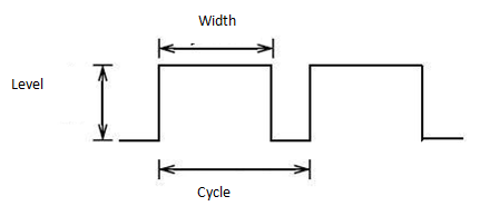
1. The amplitude of pulse width (minimum / maximum)
2. The pulse period (The reciprocal of pulse frequency in 1 second)
3. The voltage level(such as:0V-5V)
1. Sinyal genişliğinin genliği (minimum/maksimum)
2. Sinyal periyodu (1 saniyedeki sinyal frekansının karşılığı)
3. Gerilim seviyesi (örneğin: 0V-5V)
There are 6 PMW interfaces on Arduino, namely digital pin 3, 5, 6, 9, 10, and 11. In previous experiments, we have done "button-controlled LED", using digital signal to control digital pin. This time, we will use a potentiometer to control the brightness of LED.
Arduino'da dijital pin 3, 5, 6, 9, 10 ve 11 olarak adlandırılan6 PMW arayüzü vardır. Önceki deneyde, dijital sinyal kullanarak dijital pin kontrollü LED yaptık. Bu kez LED'in parlaklığını kontrol etmek için bir potansiyometre kullanacağız.
Hardware Required: / Gerekli Donanım
1. Potentiometer*1
2. Red M5 LED*1
3. 220? resistor
4. Breadboard*1
5. Breadboard jumper wires*several
1. Potansiyometre * 1
2. Kırmızı M5 LED * 1
3. 220 Ohm direnç
4. Breadboard * 1
5. Breadboard jumper kablo * birkaç adet
The input of potentiometer is analog, so we connect it to analog port, and LED to PWM port. Different PWM signal can regulate the brightness of the LED.
Potansiyometrenin girişi analogdur, bu yüzden onu analog porta ve LED'i PWM portuna bağlarız. Farklı PWM sinyali LED'in parlaklığını değiştirebilir.
Connection for UNO R3: / UNO R3 için Bağlantı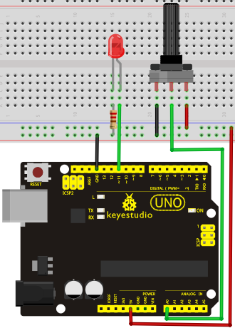
Sample Code: / Örnek Kod
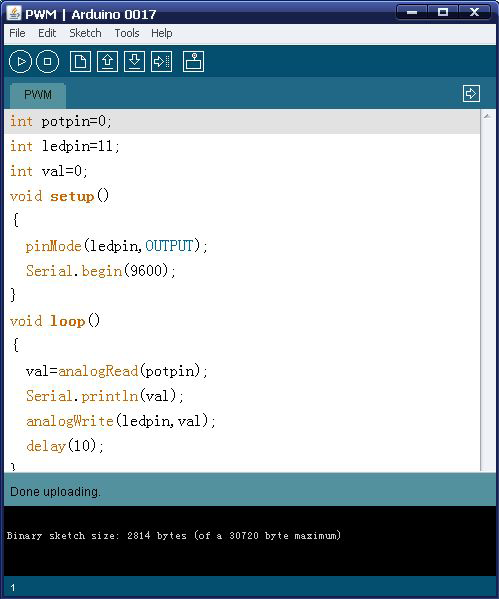
In the program compiling process, we will use the analogWrite (PWM interface, analog value) function. In this experiment, we will read the analog value of the potentiometer and assign the value to PWM port, so there will be corresponding change to the brightness of the LED. One final part will display the analog value on the screen. You can consider this as the "analog value reading" project adding the PWM analog value assigning part. Below is a sample program for your reference.
Program derleme sürecinde, analogWrite (PWM arayüzü, analog değer) fonksiyonunu kullanacağız. Bu deneyde, potansiyometrenin analog değerini okutup bu değeri PWM portuna atayacağız, böylece LED'in parlaklığında ilgili bir değişiklik olacaktır. En son ekranda analog değerini gözleyeceğiz. Bunu, PWM analog değer atama da eklenmiş, "analog değer okuma" projesi olarak düşünebilirsiniz. Aşağıdaki referans için örnek bir programdır.
int potpin=0;// initialize analog pin 0
int ledpin=11;//initialize digital pin 11(PWM output)
int val=0;// Temporarily store variables' value from the sensor
void setup()
{
pinMode(ledpin,OUTPUT);// define digital pin 11 as "output”
Serial.begin(9600);// set baud rate at 9600
// attention: for analog ports, they are automatically set up as "input”
}
void loop()
{

val=analogRead(potpin);// read the analog value from the sensor and assign it to val
Serial.println(val);// display value of val
analogWrite(ledpin,val/4);// turn on LED and set up brightness(maximum output of PWM is 255)
delay(10);// wait for 0.01 second
}
Result: / Sonuç
After uploading the program, when you rotate the potentiometer knob, you can see the value change, and also obvious change of the LED brightness.
Programı yükledikten sonra, potansiyometre düğmesini döndürdüğünüzde, değer değişimini ve ayrıca LED parlaklığının belirgin değişimini görebilirsiniz.
Project 4: Traffic Light / Trafik Işıkları
Introduction: / Tanıtım
In the previous program, we have done the LED blinking experiment with one LED. Now, it’s time to up the stakes and do a bit more complicated experiment-traffic light. Actually, these two experiments are similar. While in this traffic light experiment, we use 3 LEDs with different color rather than one LED.
Önceki programda, bir LED kullanarak yanıp sönen LED deneyi yaptık. Şimdi, zorlukları artırmanın ve biraz daha karmaşık deney olan trafik ışığı yapmanın zamanı geldi. Aslında, bu iki deney birbirine benziyor. Bu trafik ışığı deneyinde, bir LED yerine farklı renkte 3 LED kullanıyoruz.
Hardware Required: / Gerekli Donanım
1. Arduino board *1
2. USB cable *1
3. Red M5 LED*1
4. Yellow M5 LED*1
5. Green M5 LED*1
6. 220? resistor *3
7. Breadboard*1
8. Breadboard jumper wires* several
1. Arduino kart * 1
2. USB kablosu * 1
3. Kırmızı M5 LED * 1
4. Sarı M5 LED * 1
5. Yeşil M5 LED * 1
6. 220 Ohm direnç * 3
7. Breadboard * 1
8. Breadboard jumper kablosu * birkaç adet
Connection for UNO R3: / UNO R3 Bağlantısı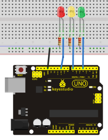
Sample Code: / Örnek Kod
Since it is a simulation of traffic light, the blinking time of each LED should be the same with those in traffic light system. In this program, we use Arduino delay () function to control delay time, which is much simpler than C language.
Trafik ışığının bir simülasyonu olduğundan, her bir LED'in yanıp sönme süresi trafik ışığı sistemindekiyle aynı olmalıdır. Bu programda, C dilinden daha basit olarak, gecikme süresini kontrol etmek için Arduino delay () fonksiyonunu kullanıyoruz.
int redled =10; // initialize digital pin 8.
int yellowled =7; // initialize digital pin 7.
int greenled =4; // initialize digital pin 4.
void setup()
{
pinMode(redled, OUTPUT);// set the pin with red LED as "output”
pinMode(yellowled, OUTPUT); // set the pin with yellow LED as "output”
pinMode(greenled, OUTPUT); // set the pin with green LED as "output”
}
void loop()
{
digitalWrite(greenled, HIGH);//// turn on green LED
delay(5000);// wait 5 seconds

digitalWrite(greenled, LOW); // turn off green LED
for(int i=0;i<3;i++)// blinks for 3 times
{
delay(500);// wait 0.5 second
digitalWrite(yellowled, HIGH);// turn on yellow LED
delay(500);// wait 0.5 second
digitalWrite(yellowled, LOW);// turn off yellow LED
}
delay(500);// wait 0.5 second
digitalWrite(redled, HIGH);// turn on red LED
delay(5000);// wait 5 second
digitalWrite(redled, LOW);// turn off red LED
}
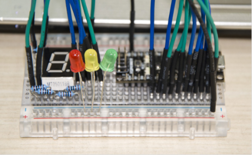
Result: / Sonuç
When the uploading process is completed, you can see traffic lights of your own design.
Note: this circuit design is very similar with the one in LED chasing effect.
The green light will be on for 5 seconds, and then off, followed by the yellow light blinking for 3 times, and then the red light is on for 5 seconds, repeatedly forming a cycle.
Experiment is now completed.
Yükleme işlemi tamamlandığında, kendi tasarımınız olan trafik ışıklarını görebilirsiniz.
Not: Bu devre tasarımı LED takip efektindeki ile çok benzer.
Yeşil ışık 5 saniye boyunca yanacak ve ardından sönecek, ardından sarı ışık 3 kez yanıp sönecek ve ardından kırmızı ışık 5 saniye boyunca yanacak ve bu şekilde tekrarlayan bir döngü oluşacaktır.
Deney şimdi tamamlandı.
Project 5: LED Chasing Effect / LED Takip Efekti
Introduction: / Tanıtım
We often see billboards composed of colorful LEDs. They are constantly changing to form various effects. In this experiment, we compile a program to simulate chase effect.
Sık sık renkli LED'lerden oluşan reklam panoları görürüz. Çeşitli efektler oluşturmak için sürekli değişiyorlar. Bu deneyde,bu efektleri elde etmek için bir program derledik.
Hardware Required: / Gerekli Donanım
1. Led x6
2. 220? resistor x6
3. Colorful breadboard wires
1. Led x 6
2. 220 Ohm direnç x 6
3. Renkli breadboard kabloları
Connection for UNO R3: / UNO R3 Bağlantısı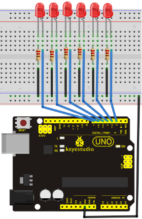
Sample Code: / Örnek Kod
int BASE = 2 ;  // the I/O pin for the first LED
int NUM = 6;   // number of LEDs

void setup()
{
   for (int i = BASE; i < BASE + NUM; i ++)
   {
     pinMode(i, OUTPUT);   // set I/O pins as output
   }
}

void loop()
{
   for (int i = BASE; i < BASE + NUM; i ++)
   {
     digitalWrite(i, LOW);    // set I/O pins as "low”, turn off LEDs one by one.
     delay(200);        // delay
   }
   for (int i = BASE; i < BASE + NUM; i ++)
   {
     digitalWrite(i, HIGH);    // set I/O pins as "high”, turn on LEDs one by one
     delay(200);        // delay
   }
}
Result: / Sonuç
You can see the LEDs blink by sequence.
LED'lerin sırayla yanıp söndüğünü görebilirsiniz.
Project 6: Button-controlled LED / Buton ile LED Kontrolü
Introduction: / Tanıtım
I/O port means interface for INPUT and OUTPUT. Up until now, we have only used its OUTPUT function. In this experiment, we will try to use the input function, which is to read the output value of device connecting to it. We use 1 button and 1 LED using both input and output to give you a better understanding of the I/O function. Button switches, familiar to most of us, are a switch value (digital value) component. When it's pressed,the circuit is in closed (conducting) state.
I / O (Input/Output) portu GİRİŞ ve ÇIKIŞ için arabirim anlamına gelir. Şimdiye kadar yalnızca OUTPUT işlevini kullandık. Bu deneyde, bağlı bir cihazın çıkış değerini okumak için kartın giriş işlevini kullanmaya çalışacağız. I / O işlevini daha iyi anlayabilmeniz için hem girişi hem de çıkışı kullanmak üzere 1 buton (düğme) ve 1 LED bağlayacağız. Çoğumuzun bildiği buton anahtarları, aslında bir anahtar değer (dijital değer) bileşenidir. Basıldığında, devre kapalı (iletken) durumdadır.
Hardware Required: / Gerekli Donanım
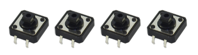
1. Button switch*1
2. Red M5 LED*1
3. 220? resistor*1
4. 10K? resistor*1
5. Breadboard*1
6. Breadboard jumper wires*several
1. Buton anahtarı * 1
2. Kırmızı M5 LED * 1
3. 220 Ohm direnç * 1
4. 10K Ohm direnç * 1
5. Breadboard * 1
6. Breadboard jumper kablo * birkaç adet
Connection for UNO R3: / UNO R3 Bağlantısı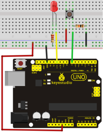
Sample Code: / Örnek Kod
Now, let's begin the compiling. When the button is pressed, the LED will be on. Based on the previous study, the coding may be easy for you. In this program, we add a statement of judgment. Here, we use an if () statement.
Arduino IDE is based on C language, so statements of C language such as while, switch etc. can certainly be used for Arduino program.
When we press the button, pin 7 will output high level. We can program pin 11 to output high level and turn on the LED. When pin 7 outputs low level, pin 11 also outputs low level and the LED remains off.
Şimdi Kod derlemeye başlayalım. Düğmeye basıldığında, LED yanacaktır. Önceki çalışmaya bakarak, bu kodlama sizin için kolay gelebilir. Bu programda, bir kural ekleyeceğiz. Burada bir if () ifadesi kullanacağız.
Arduino IDE, C diline dayanmaktadır, bu nedenle, while, switch vb. gibi C dili ifadeleri kesinlikle Arduino programı için kullanılabilir.
Düğmeye bastığımızda, pin 7 yüksek seviye sinyal çıkacaktır. Bu durumdayken Pin 11'i yüksek seviye sinyal çıkacak ve LED'i açacak şekilde programlayabiliriz. Pin 7 düşük seviye çıktığı zaman pin 11 de düşük seviye çıkışı verir ve LED kapalı kalır.
int ledpin=11;// pin 11'i aç
int inpin=7;// pin 7'yi aç
int val;// value(değer) tanımla
void setup()
{
pinMode(ledpin,OUTPUT);// LED pini "çıkış" olarak ata
pinMode(inpin,INPUT);// button pini "giriş” olarak ata

}
void loop()
{
val=digitalRead(inpin);// pin 7'nin seviye değerini oku ve if'i val değerine ata
if(val==LOW)// buton basılı mı diye kontrol et, basılıysa LED'i yak, yoksa söndür.
{ digitalWrite(ledpin,LOW);}
else
{ digitalWrite(ledpin,HIGH);}
}
Result: / Sonuç
When the button is pressed, LED is on, otherwise, LED remains off. So the button controlled LED experiment is completed. The simple principle of this experiment is widely used in a variety of circuit and electric appliances. You can easily come across it in your everyday life. One typical example is when you press a certain key of your phone, the backlight will be on.
Düğmeye basıldığında LED yanar, aksi halde LED kapalı kalır. Böylece buton kontrollü LED deneyi tamamlandı. Bu deneyin basit prensibi çeşitli devre ve elektrikli cihazlarda yaygın olarak kullanılmaktadır. Günlük yaşamınızda kolayca karşılaşabilirsiniz. Tipik bir örnek, telefonunuzun belirli bir tuşuna bastığınız zaman, arka ışık yanacaktır.
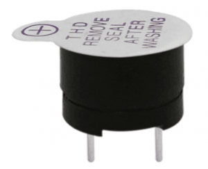
Project 7: Active Buzzer / Aktif Buzzer
Introduction: / Tanıtım
Active buzzer is widely used as a sound making element on computer, printer, alarm, electronic toy, telephone, timer, etc. It has an inner vibration source. Simply connect it with 5V power supply, it can buzz continuously.
Aktif buzzer (Sesli uyarıcı); bilgisayar, yazıcı, alarm, elektronik oyuncak, telefon, zamanlayıcı, vb. cihazlarda sesli uyarıcı olarak yaygın şekilde kullanılır. İç titreşim kaynağına sahiptir. Basitçe 5V güç kaynağı bağlayın, sürekli vızıltı sesi (buzz) verebilir.
Hardware Required: / Gerekli Donanım
1. Buzzer*1
2. Key *1
3. Breadboard*1
4. Breadboard jumper wires*several
1. Buzzer * 1
2. Anahtar * 1
3. Breadboard * 1
4. Breadboard jumper kablo * birkaç adet
Connection for UNO R3: / UNO R3 Bağlantısı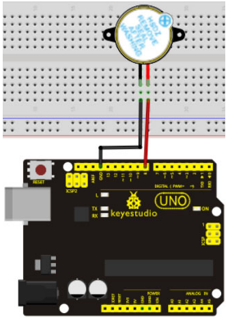
When connecting the circuit, pay attention to the positive & the negative poles of the buzzer. In the photo, you can see there are red and black lines. When the circuit is finished, you can begin the programming.
Devreyi bağlarken, buzzerin pozitif ve negatif kutuplarına dikkat edin. Fotoğrafta kırmızı ve siyah çizgiler olduğunu görebilirsiniz. Devre tamamlandığında, programlamaya başlayabilirsiniz.
Sample Code: / Örnek Kod
Program is simple. You can control the buzzer by outputting high/low level.
Program basittir. Buzzer'ı yüksek/düşük seviye sinyalle kontrol edebilirsiniz.
int buzzer=8;// buzzer kontrol etmek üzere I/O pini başlat
void setup()
{
  pinMode(buzzer,OUTPUT);// pin modunu "çıkış” olarak ayarla
}
void loop()
{
digitalWrite(buzzer, HIGH); // ses oluştur
}
Result: / Sonuç
After downloading the program, the buzzer experiment is completed. You can see the buzzer is ringing.
Programı yükledik ve buzzer deneyi tamamlandı. Buzzer'ın öttüğünü duyabilirsiniz
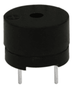
Project 8: Passive Buzzer / Pasif Buzzer
Introduction: / Tanıtım
You can use Arduino to make many interactive works.The most commonly used example is acoustic-optic display. Previous experiments has something to do with LED. However, the circuit in this experiment can produce sound. Normally, the experiment is done with a buzzer or a speaker while buzzer is simpler and easier to use. The buzzer we introduced here is a passive buzzer. It cannot be actuated by itself, but by external pulse frequencies. Different frequencies produce different sounds. You can use Arduino to code the melody of a song, which is quite fun and simple.
Arduino'yu birçok interaktif çalışma yapmak için kullanabilirsiniz. En sık kullanılan örnek akustik-optik ekrandır. Önceki deneyler LED ile ilgiliydi. Fakat, bu deney devresi ses üretebilir. Normalde bu deney basit ve kolay olması açısından bir buzzer ile yapılır, veya bir hoparlör ile de yapılabilir. Burada tanıttığımız pasif bir buzzer'dır. Kendiliğinden değil, harici sinyal frekansları tarafından çalıştırılabilir. Farklı frekanslar farklı sesler üretir. Arduino'yu, çok eğlenceli ve basit bir şarkının melodisini kodlamak için kullanabilirsiniz.
Hardware Required: / Gerekli Donanım
1.Passive buzzer*1
2. Key *1
3. Breadboard*1
4. Breadboard jumper wires* several
1. Pasif buzzer * 1
2. Anahtar * 1
3. Breadboard * 1
4. Breadboard jumper kablo * birkaç adet
Connection for UNO R3: / UNO R3 Bağlantısı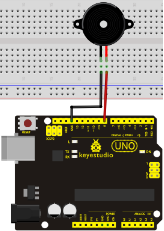
Sample Code: / Örnek Kod
int buzzer=8;// buzzer için dijital I/O portunu seçin
void setup()
{
pinMode(buzzer,OUTPUT);// dijital IO pin modunu ayarlayın, çıkış için OUTPUT
}
void loop()
{ unsigned char i,j;// değişkeni tanımla
while(1)
{ for(i=0;i<80;i++)// frekans ses çıkışı verin
{ digitalWrite(buzzer,HIGH);// ses çıkar
delay(1);// 1ms gecik
digitalWrite(buzzer,LOW);// sus
delay(1);// 1ms gecik
}
for(i=0;i<100;i++)// frekans ses çıkışı verin
{ digitalWrite(buzzer,HIGH);// sound
delay(2);//2ms delay
digitalWrite(buzzer,LOW);//not sound
delay(2);//2ms delay
}
}
}
Result: / Sonuç
After downloading the program, the buzzer experiment is completed.
Programı yükledik ve sonra buzzer deneyi tamamlandı.
Project 9: RGB LED / RGB LED
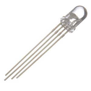
Introduction: / Tanıtım
Tricolor principle to display various colors;
PWM controlling ports to display full color;
Can be driven directly by Arduino PWM interfaces.
Çeşitli renkleri görüntülemek için üç-renk prensibi;
Tam renkli görüntülemek için PWM kontrol portları;
Doğrudan Arduino PWM arayüzleri tarafından yönetilebilir.
Hardware Required: / Gerekli Donanım
- Arduino controller × 1
- USB cable × 1
- Full-color LED module × 1
- Arduino denetleyicisi × 1
- USB kablosu × 1
- Tam-renkli LED modülü × 1
Connection for UNO R3: / UNO R3 Bağlantısı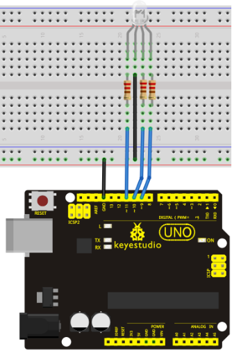
Sample Code: / Örnek Kod
int redpin = 11; // kırmızı LED için pin seçin
int bluepin =10; // mavi LED için pin seçin
int greenpin =9;// yeşil LED için pin seçin

int val;

void setup() {
  pinMode(redpin, OUTPUT);
  pinMode(bluepin, OUTPUT);
  pinMode(greenpin, OUTPUT);
  Serial.begin(9600);
}

void loop()
{
for(val=255; val>0; val--)
  {
   analogWrite(11, val);
   analogWrite(10, 255-val);
   analogWrite(9, 128-val);
   delay(1);
  }
for(val=0; val<255; val++)
  {
   analogWrite(11, val);
   analogWrite(10, 255-val);
   analogWrite(9, 128-val);
   delay(1);
  }
 Serial.println(val, DEC);
}
Result:
Directly copy the above code into arduino IDE, and click upload ![]() , wait for a few seconds, you can see a full-color LED.
, wait for a few seconds, you can see a full-color LED.
Yukarıdaki kodu doğrudan arduino IDE'ye kopyalayın ve yükleme dümesine ![]() tıklayın, birkaç saniye bekleyin, tam-renkli bir LED göreceksiniz.
tıklayın, birkaç saniye bekleyin, tam-renkli bir LED göreceksiniz.
Project 10: Photo Resistor / Fotorezistör
Introduction: / Tanıtım
After completing all the previous experiments, you may acquire some basic understanding and knowledge about Arduino application. We have introduced digital input and output, analog input and PWM. Now, let's begin the learning of sensors applications.
Photo resistor (Photovaristor) is a resistor whose resistance varies from the different incident light strength. It's made based on the photoelectric effect of semiconductor. If the incident light is intense, its resistance reduces; if the incident light is weak, the resistance increases. Photovaristor is commonly applied in the measurement of light, light control and photovoltaic conversion (convert the change of light into the change of electricity).
Photo resistor is also widely applied to various light control circuit, such as light control and adjustment, optical switches, etc.We will start with a relatively simple experiment regarding to photovaristor application. Photovaristor is an element that will change its resistance as light strength changes. So need to read the analog values. You can refer to the PWM experiment, replacing the potentiometer with photovaristor. When there is change in light strength, it will cause corresponding change on the LED.
Önceki tüm deneyleri tamamladıktan sonra, Arduino uygulaması hakkında temel bir anlayış ve bilgi edinmiş olmalısınız. Dijital giriş ve çıkış, analog giriş ve PWM'yi tanıttık. Şimdi, sensör uygulamalarını öğrenmeye başlayalım.
Fotorezistör (Fotovaristör), direnci farklı ışık güçlerinde farklı direnci olan bir dirençtir. Yarı iletken fotoelektrik etkisi esas alınarak yapılmıştır. Işık yoğunsa, direnci azalır; ışık zayıfsa direnç artar. Fotorezistör, genellikle ışık, ışık kontrolü ve fotovoltaik dönüşüm (ışığın değişimini elektrik değişikliğine dönüştürür) ölçümlerinde uygulanır .
Fotorezistör, ayrıca ışık kontrolü ve ayarı, optik anahtarlar vb. gibi çeşitli ışık kontrol devrelerinde yaygın olarak uygulanır. Fotorezistör uygulamasına oldukça basit bir deneyle başlayacağız. Fotorezistör, ışık gücü değiştikçe direncini değiştiren bir elementtir. Bu durumda analog değerleri okumalıyız. Önceki PMW deneyindeki potansiyometreyi, fotorezistör ile yer değiştirebiliriz. Işık gücünde bir değişiklik olduğunda, LED üzerinde ilgili bir değişikliğe neden olacaktır.
Hardware Required: / Gerekli Donanım
- Photo resistor*1
- Red M5 LED*1
- 10K?resistor*1
- 220?resistor*1
- Breadboard*1
- Breadboard jumper wires*several
- Fotorezistör * 1
- Kırmızı M5 LED * 1
- 10 KOhm Direnç * 1
- 220 Ohm Direnç * 1
- Breadboard * 1
- Breadboard jumper kablo * birkaç adet
Connection for UNO R3: / UNO R3 Bağlantısı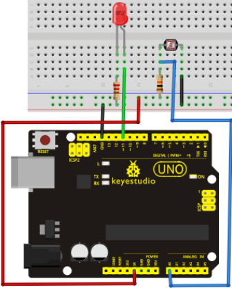
Sample Code: / Örnek Kod
After the connection, let's begin the program compiling. The program is similar to the one of PWM. For change detail, please refer to the sample program below.
Bağlantıdan sonra program derlemeye başlayalım. Program PWM programına benzer. Değişiklik detayı için lütfen aşağıdaki örnek programa bakın.
int potpin=0;// initialize analog pin 0, connected with photovaristor
int ledpin=11;// initialize digital pin 11, output regulating the brightness of LED
int val=0;// initialize variable va
void setup()
{
pinMode(ledpin,OUTPUT);// set digital pin 11 as "output”
Serial.begin(9600);// set baud rate at "9600”
}
void loop()
{
val=analogRead(potpin);// read the analog value of the sensor and assign it to val
Serial.println(val);// display the value of val
analogWrite(ledpin,val/4);// turn on the LED and set up brightness(maximum output value 255)
delay(10);// wait for 0.01
}
Result:
After downloading the program, you can change the light strength around the photovaristor and see corresponding brightness change of the LED. Photovaristors has various applications in our everyday life. You can make other interesting interactive projects based on this one.
Programı indirdikten sonra, fotorezistöre yansıyan ışık gücünü değiştirebilir ve LED'de meydana getirdiği parlaklık değişimini görebilirsiniz. Fotorezistörlerin günlük yaşamımızda çeşitli uygulama alanları vardır. Buna dayanarak başka ilginç projeler de yapabilirsiniz.
Project 11: Flame Sensor / Alev Sensörü
Introduction: / Tanıtım
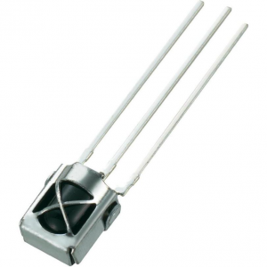
Flame sensor (Infrared receiving triode) is specially used on robots to find the fire source. This sensor is of high sensitivity to flame.
Alev sensörü (Kızılötesi alıcı triyot) yangın kaynağını bulmak için özellikle robotlarda kullanılır. Bu sensör aleve karşı yüksek hassasiyete sahiptir.
Working Principle: / Çalışma Prensibi
Flame sensor is based on the principle that infrared ray is highly sensitive to flame. It has an infrared receiving tube specially designed to detect fire, and then convert the flame brightness into fluctuating level signal. The signals are then input into the central processor and be dealt with accordingly.
Alev sensörü, alevlerden kızılötesi ışınınların yayılması ilkesine dayanır. Özel olarak alev algılamak için tasarlanmış bir kızılötesi alıcı tüpe sahiptir ve daha sonra alev parlaklığını dalgalı seviye sinyaline dönüştürür. Sinyaller daha sonra merkezi işlemciye girilir ve buna göre ele alınır.
Sensor Connection: / Sensör Bağlantısı
The shorter lead of the receiving triode is for negative, the other one for positive. Connect negative to 5V pin, positive to resistor; connect the other end of the resistor to GND, connect one end of a jumper wire to a clip which is electrically connected to sensor positive, the other end to analog pin. As shown below:
Alıcı triyot sensörün daha kısa ayağı negatif, diğeri pozitiftir. Direncin bir ucunu sensörün pozitifine, diğer ucunu GND'ye (toprağa) bağlayın. Sensörün negatif ayağını 5V pine bağlayın; direncin , bir jumper kablo ile sensörün pozitif uzantısından bir hat alıp analog pine girin. Aşağıda gösterildiği gibi: 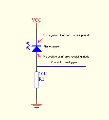
Hardware Required: / Gerekli Donanım
1. Flame sensor*1
2. Buzzer*1
3. 10K resistor*1
4. Breadboard jumper wires* several
1. Alev sensörü * 1
2. Buzzer * 1
3. 10K direnç * 1
4. Breadboard jumper kablo* birkaç adet
Experiment Connection: / Deney Bağlantısı
1)Connecting buzzer:
Connect the controller board, prototype board, breadboard and USB cable according to the Arduino tutorial. Connect the buzzer to digital pin 8.
2)Connecting flame sensor:
Connect the sensor to analog pin 0.
1) Buzzer'ın bağlanması:
Denetleyici kartı, prototip kartı, breadboardu ve USB kablosunu aşağıdaki görsele göre bağlayın. Buzzer'ı dijital pin 8'e bağlayın.
2) Alev sensörünün bağlanması:
Sensörü analog pin 0'a bağlayın.
Connection for UNO R3: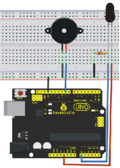
Experiment Principle: / Deney Prensibi
When it's approaching a fire, the voltage value the analog port reads differs. If you use a multimeter, when there is no fire approaching, the voltage it reads is around 0.3V; when there is fire approaching, the voltage it reads is around 1.0V. The nearer the fire is, the higher the voltage is. So in the beginning of the program, you can initialize voltage value i (no fire value); Then, continuously read the analog voltage value j and obtain difference value k=j-i; compare k with 0.6V (123 in binary) to determine whether there is a fire approaching or not; if yes, the buzzer will buzz.
Ateşe yaklaşırken, analog portun okuduğu voltaj değeri değişir. Bir multimetre kullanıyorsanız gözleyebilirsiniz, yangın olmadığında okuduğu voltaj 0.3V civarındadır; alev varken okuduğu voltaj 1.0V civarındadır. Yangın ne kadar yakınsa, voltaj da o kadar yüksek olur. Aşağıdaki programın başında, örneğin i (alev yok değeri) voltaj değerini girebilirsiniz ; Ardından, sürekli olarak analog voltaj değerini (j) okur ve k = j-i farkını elde eder; yangın olup olmadığını belirlemek için k'yı okur ve karşılaştırma yapar; alev varsa buzzer'dan ses duyulur.
Sample Code: / Örnek Kod
int flame=0;// select analog pin 0 for the sensor
 int Beep=9;// select digital pin 9 for the buzzer
 int val=0;// initialize variable
 void setup()
{
  pinMode(Beep,OUTPUT);// set LED pin as "output”
 pinMode(flame,INPUT);// set buzzer pin as "input”
 Serial.begin(9600);// set baud rate at "9600”
 }
void loop()
{
  val=analogRead(flame);// read the analog value of the sensor
  Serial.println(val);// output and display the analog value
  if(val>=600)// when the analog value is larger than 600, the buzzer will buzz
  {
   digitalWrite(Beep,HIGH);
   }else
   {
     digitalWrite(Beep,LOW);
    }
   delay(500);
}
Result: / Sonuç
This program can simulate an alarm when there is a fire. Everything is normal when there is no fire; when there is fire, the alarm will be set off immediately.
Bu program, yangın durumu olduğunda bir alarm tetikleyebilir. Alev olmadığında her şey normaldir; Yangın olduğunda, alarm derhal devreye girer.
Project 12: LM35 Temperature Sensor / LM35 Sıcaklık Sensörü
Introduction: / Tanıtım
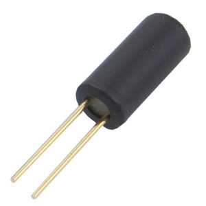
LM35 is a common and easy-to-use temperature sensor. It does not require other hardware. You just need an analog port to make it work. The difficulty lies in compiling the code to convert the analog value it reads to celsius temperature.
LM35, yaygın ve kullanımı kolay bir sıcaklık sensörüdür. Başka bir donanım gerektirmez. Sadece çalışması için bir analog bağlantı noktasına ihtiyacınız var. Zorluk, okuduğu analog değeri santigrat sıcaklığa dönüştürmek için kodun derlenmesinde yatmaktadır. 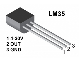
Hardware Required: / Gerekli Donanım
1. LM35*1
2. Breadboard*1
3. Breadboard jumper wires*several
1. LM35*1
2. Breadboard*1
3. Breadboard jumper kablo * birkaç adet
Connection for UNO R3: / UNO R3 Bağlantısı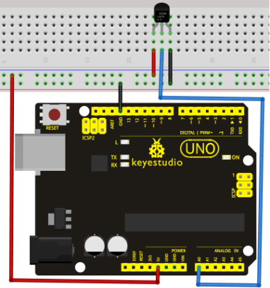
Sample Code: / Örnek Kod
int potPin = 0; // initialize analog pin 0 for LM35 temperature sensor
void setup()
{
Serial.begin(9600);// set baud rate at”9600”
}
void loop()
{
int val;// define variable
int dat;// define variable
val=analogRead(0);// read the analog value of the sensor and assign it to val
dat=(125*val)>>8;// temperature calculation formula
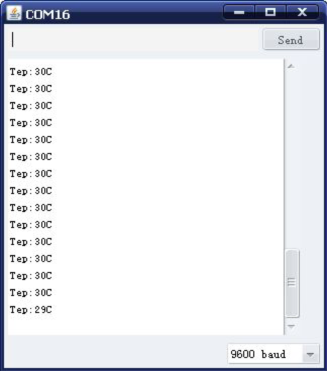
Serial.print("Tep:");// output and display characters beginning with Tep
Serial.print(dat);// output and display value of dat
Serial.println("C");// display "C” characters
delay(500);// wait for 0.5 second
}
Result: / Sonuç
After downloading the program, you can open the monitoring window to see the current temperature.
Programı yükledikten sonra, mevcut sıcaklığı görmek için monitör penceresini açabilirsiniz.
Project 13: Tilt Switch / Eğim Kontağı
Introduction: / Tanıtım
Tilt switch controlling the LED ON and OFF.
LED'i AÇIK ve KAPALI olarak kontrol eden eğim anahtarı.
Hardware Required: / Gerekli Donanım
1. Ball switch*1
2. Led *1
3. 220? resistor*1
4. 10K? resistor*1
5. Breadboard jumper wires:several
1. Eğim sensörü (Bilyeli anahtar) * 1
2. Led *1
3. 220 Ohm direnç * 1
4. 1 0KOhm direnç * 1
5. Breadboard jumper kablo * birkaç adet
Connection for UNO R3: / UNO R3 Bağlantısı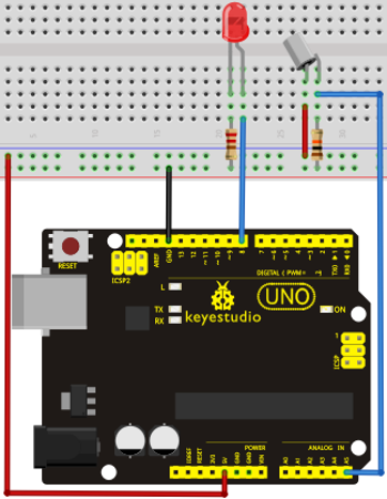
Connect the controller board, shield, breadboard and USB cable according to Arduino tutorial. Connect the LED to digital pin 8, ball switch to analog pin 5.
Denetleyiciyi, shield'i, breadboard'u ve USB kablosunu yukarıdaki görsele göre bağlayın. LED'i dijital pin 8'e, bilyeli anahtarı analog pin 5'e bağlayın.
Experiment Principle: / Deney prensibi
When one end of the switch is below horizontal position, the switch is on. The voltage of the analog port is about 5V (1023 in binary). The LED will be on. When the other end of the switch is below horizontal position, the switch is off. The voltage of the analog port is about 0V (0 in binary). The LED will be off. In the program, we determine whether the switch is on or off according to the voltage value of the analog port, whether it's above 2.5V (512 in binary) or not.
Anahtarın bir ucu yatay konumun altında olduğunda, anahtar devreye girer ve analog portun voltajı yaklaşık 5V'tur (analog veri olarak 1023). LED yanacaktır. Anahtarın diğer ucu yatay konumun altında olduğunda, anahtar devre dışı kalır ve analog portun voltajı 0V olur (analog veri olarak 0). LED sönecektir. Programda, anahtarın açık veya kapalı olup olmadığını, analog portun voltaj değerinin 2,5V'un (analog veri olarak 512) üstünde ya da altında olmasına göre belirleriz.
Sample Code:
void setup()
{
  pinMode(8,OUTPUT);// set digital pin 8 as "output”
}
void loop()
{
int i;// define variable i
while(1)
{
  i=analogRead(5);// read the voltage value of analog pin 5
  if(i>512)// if larger that 512(2.5V)
  {
    digitalWrite(8,LOW);// turn on LED
  }
  else// otherwise
  {
    digitalWrite(8,HIGH);// turn off LED
  }
 }
}
Result: / Sonuç
Hold the breadboard with your hand. Tilt it to a certain extent, the LED will be on. If there is no tilt, the LED will be off.
The principle of this experiment can be applied to relay control.
Experiment is completed.
Breadboard'u elinizle tutun. Bir dereceye kadar eğin, LED yanacaktır. Eğim yoksa, LED sönecektir.
Bu deneyin prensibi röle kontrolüne uygulanabilir.
Deney tamamlandı.
Project 14: IR Remote Control / IR Uzaktan Kontrol
Introduction: / Tanıtım
What is an infrared receiver?
The signal from the infrared remote controller is a series of binary pulse code. To avoid interference from other infrared signals during the wireless transmission, the signal is pre-modulate at a specific carrier frequency and then send out by an infrared emission diode. The infrared receiving device needs to filter out other wave and receive signal at that specific frequency and modulate it back to binary pulse code, known as demodulation.
Kızılötesi alıcı nedir?
Kızılötesi uzaktan kumandalardan gelen sinyaller seri ikilik-tabanlı sinyal kodlarıdır. Kablosuz iletişim sırasında diğer kızılötesi sinyallerin karışmasını önlemek için, sinyal belirli bir taşıyıcı frekansta önceden modüle edilir ve daha sonra bir kızılötesi yayıcı diyod ile gönderilir. Kızılötesi alıcı cihazın ise gelen sinyal dalgasını filtrelemesi ve belirli bir frekansta sinyal alması ve demodülasyon olarak bilinen ikilik-tabanlı sinyal koduna geri çevirmesi gerekir.
Working Principle:
The built-in receiver converts the light signal it received from the sender into feeble electrical signal. The signal will be amplified by the IC amplifier. After automatic gain control, band-pass filtering, demodulation, wave shaping, it returns to the original code. The code is then input to the code identification circuit by the receiver's signal output pin.
Dahili alıcı, göndericiden aldığı ışık sinyalini zayıf elektrik sinyaline dönüştürür. Sinyal, IC yükselticisi tarafından yükseltilecektir. Otomatik kazanç kontrolü, bant filtreleme, demodülasyon, dalga şekillendirmeden sonra orijinal koda döner. Kod daha sonra alıcının sinyal çıkış pini tarafından kod tanımlama devresine yönlendirilir.
The pin and the connection of the infrared receiving head.
Kızılötesi alıcı başlığın pini ve bağlantısı.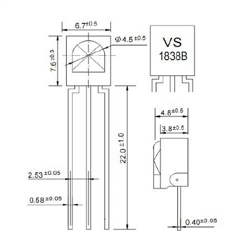
Pin and wiring of infrared receiver:
Kızılötesi alıcının pini ve bağlantısı: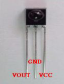
Infrared receiver has 3 pins.
When you use it, connect VOUT to analog pin, GND to GND, VCC to +5V.
Kızılötesi alıcı 3 pinlidir.
Kullanırken, VOUT'u analog pine, GND'yi GND'ye, VCC'yi + 5V'a bağlayın.
Hardware Required: / Gerekli Donanım
- Infrared remote controller x1
- Infrared receiver x1
- LED x6
- 220? resistor x6
- Multi-color breadboard wires x several
- Kızılötesi uzaktan kumanda x 1
- Kızılötesi alıcı x 1
- LED x 6
- 220 Ohm direnç x 6
- Farklı renk breadboard kabloları x birkaç adet
Connection Diagram: / Bağlantı Şeması
First, connect the controller board; then connect the infrared receiver as the above mentioned, connect VOUT to digital pin 11, connect the LEDs with resistors and connect the resistors to pin2,3,4,5,6,7.
İlk önce denetleyiciyi bağlayın, daha sonra kızılötesi alıcıyı yukarıda belirtildiği gibi bağlayın; VOUT'u dijital pin 11'e bağlayın, LED'leri aşağıdaki gibi dirençlerle bağlayın ve dirençleri pin 2,3,4,5,6,7'ye bağlayın.
Connection for UNO R3: / UNO R3 Bağlantısı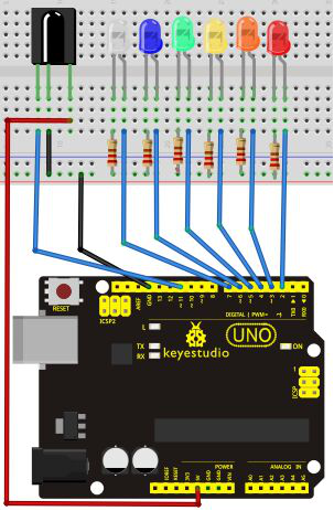
Experimental Principle: / Deney Prensibi
If you want to decode the code from a remote controller, you must first know how it's coded. The coding method we use here is NEC protocol. Below is a brief introduction.
Bir uzaktan kumandadan gelen sinyalin kodunu çözmek istiyorsanız, önce nasıl kodlandığını bilmeniz gerekir. Burada kullandığımız kodlama yöntemi NEC protokolüdür. Aşağıda bazı bilgiler verilmiştir.
- NEC protocol:
Features: / Özellikler
(1) 8 bit address and 8 bit command length
(2) address and command are transmitted twice for reliability
(3) pulse distance modulation
(4) carrier frequency of 38 KHZ
(5) bit time of 1.125ms or 2.25ms
(1) 8 bit adres ve 8 bit komut uzunluğu
(2) adres ve komut güvenilirlik için iki kez iletilir
(3) sinyal mesafesi modülasyonu
(4) 38 KHZ taşıyıcı frekansı
(5) 1.125ms veya 2.25ms bit zamanı
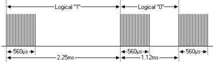
Protocol is as below: / Protokol aşağıdaki gibidir:
- Definition of logical 0 and 1 is as below
- Mantıksal değer 0 ve 1'in tanımı aşağıdaki gibidir
- Pulse transmitted when button is pressed and immediately released.
- Düğmeye anlık basılıp bırakıldığında sinyal iletilir.
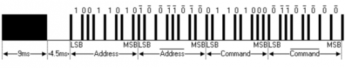
The picture above shows a typical pulse train of the NEC protocol. With this protocol the LSB is transmitted first. In this case Address $59 and Command $16 is transmitted. A message is started by a 9ms AGC burst, which was used to set the gain of the earlier IR receivers. This AGC burst is then followed by a 4.5ms space, which is then followed by the address and command. Address and Command are transmitted twice. The second time all bits are inverted and can be used for verification of the received message. The total transmission time is constant because every bit is repeated with its inverted length. If you are not interested in this reliability, you can ignore the inverted values, or you can expend the Address and Command to 16 bits each!
Yukarıdaki resim, NEC protokolünün tipik bir sinyal trenini göstermektedir. Bu protokol ile önce LSB iletilir. Bu durumda Adres $59 ve Komut $16 iletilir. Eski IR alıcılarının kazancını ayarlamak için kullanılan 9ms AGC atımı ile bir mesaj başlatılır. Bu AGC atımını 4.5ms boşluk izler, ardından adres ve komut izler. Adres ve Komut ikişer kez iletilir. İkinci kez tüm bitler ters çevrilir ve alınan mesajın doğrulanması için kullanılabilir. Toplam iletim süresi sabittir, çünkü her bit ters uzunluğu ile tekrarlanır. Bu güvenilirlikle ilgilenmiyorsanız, ters çevrilen değerleri yok sayabilir veya Adres ve Komutu her birini 16 bit olarak sarfedebilirsiniz!
- Pulse transmitted when button is pressed and released after a period of time
- Düğmeye anlık olarak basılıp bırakıldığında sinyal iletilir.
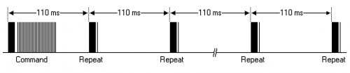
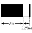
A command is transmitted only once, even when the key on the remote control remains pressed. Every 110ms a repeat code is transmitted for as long as the key remains down. This repeat code is simply a 9ms AGC pulse followed by a 2.25ms space and a 560µs burst.
Uzaktan kumandadaki tuşa basılı tutulsa bile, bir komut yalnızca bir kez iletilir. Her 110ms'de, anahtar basılı kaldığı sürece tekrar eden bir kod iletilir. Bu tekrar kodu basitçe 9ms AGC darbesidir, bunu 2.25ms boşluk ve ardından 560µs atımı izler.
- Repeat pulse
- Tekrar sinyali
Note: when the pulse enters the integrated receiver, there will be decoding, signal amplifying and wave shaping process. So you need to make sure the level of the output is just the opposite from that of the signal sending end. That is when there is no infrared signal, the output end is in high level; when there is infrared signal, the output end is in low level. You can see the pulse of the receiving end in the oscilloscope. Try to better understand the program base on what you see.
Not: Sinyal entegre alıcıya girdiğinde kod çözme, sinyal büyütme ve dalga şekillendirme işlemlerinden geçecektir. Bu nedenle, çıktının seviyesinin, sinyal gönderme ucununkinin tam tersi olduğundan emin olmanız gerekir. Kızılötesi sinyal olmadığında çıkış ucu yüksek seviyededir; Kızılötesi sinyal olduğunda, çıkış ucu düşük seviyededir. Osiloskopta alıcı ucun sinyalini görebilirsiniz. Gözlemlerinize dayanarak program temelini daha iyi anlamaya çalışın.
Sample Code: / Örnek Kod
#includeint RECV_PIN = 11; int LED1 = 2; int LED2 = 3; int LED3 = 4; int LED4 = 5; int LED5 = 6; int LED6 = 7; long on1 = 0x00FF6897; long off1 = 0x00FF9867; long on2 = 0x00FFB04F; long off2 = 0x00FF30CF; long on3 = 0x00FF18E7; long off3 = 0x00FF7A85; long on4 = 0x00FF10EF; long off4 = 0x00FF38C7; long on5 = 0x00FF5AA5; long off5 = 0x00FF42BD; long on6 = 0x00FF4AB5; long off6 = 0x00FF52AD; IRrecv irrecv(RECV_PIN); decode_results results; // Dumps out the decode_results structure. // Call this after IRrecv::decode() // void * to work around compiler issue //void dump(void *v) { // decode_results *results = (decode_results *)v void dump(decode_results *results) { int count = results->rawlen; if (results->decode_type == UNKNOWN) { Serial.println("Could not decode message"); } else { if (results->decode_type == NEC) { Serial.print("Decoded NEC: "); } else if (results->decode_type == SONY) { Serial.print("Decoded SONY: "); } else if (results->decode_type == RC5) { Serial.print("Decoded RC5: "); } else if (results->decode_type == RC6) { Serial.print("Decoded RC6: "); } Serial.print(results->value, HEX); Serial.print(" ("); Serial.print(results->bits, DEC); Serial.println(" bits)"); } Serial.print("Raw ("); Serial.print(count, DEC); Serial.print("): "); for (int i = 0; i < count; i++) { if ((i % 2) == 1) { Serial.print(results->rawbuf[i]*USECPERTICK, DEC); } else { Serial.print(-(int)results->rawbuf[i]*USECPERTICK, DEC); } Serial.print(" "); } Serial.println(""); } void setup() { pinMode(RECV_PIN, INPUT); pinMode(LED1, OUTPUT); pinMode(LED2, OUTPUT); pinMode(LED3, OUTPUT); pinMode(LED4, OUTPUT); pinMode(LED5, OUTPUT); pinMode(LED6, OUTPUT); pinMode(13, OUTPUT); Serial.begin(9600); irrecv.enableIRIn(); // Start the receiver } int on = 0; unsigned long last = millis(); void loop() { if (irrecv.decode(&results)) { // If it's been at least 1/4 second since the last // IR received, toggle the relay if (millis() - last > 250) { on = !on; // digitalWrite(8, on ? HIGH : LOW); digitalWrite(13, on ? HIGH : LOW); dump(&results); } if (results.value == on1 ) digitalWrite(LED1, HIGH); if (results.value == off1 ) digitalWrite(LED1, LOW); if (results.value == on2 ) digitalWrite(LED2, HIGH); if (results.value == off2 ) digitalWrite(LED2, LOW); if (results.value == on3 ) digitalWrite(LED3, HIGH); if (results.value == off3 ) digitalWrite(LED3, LOW); if (results.value == on4 ) digitalWrite(LED4, HIGH); if (results.value == off4 ) digitalWrite(LED4, LOW); if (results.value == on5 ) digitalWrite(LED5, HIGH); if (results.value == off5 ) digitalWrite(LED5, LOW); if (results.value == on6 ) digitalWrite(LED6, HIGH); if (results.value == off6 ) digitalWrite(LED6, LOW); last = millis(); irrecv.resume(); // Receive the next value } }
Program Function / Programın İşlevi
Decode the coded pulse signal emitted by the remote controller, then execute corresponding action according to the results of the decoding. In this way, you are able to control your device with remote control.
Uzaktan kumanda tarafından yayılan kodlanmış nabız sinyalinin kodunu çözün, ardından kod çözme sonuçlarına göre ilgili işlemi uygulayın. Bu sayede cihazınızı uzaktan kumanda ile kontrol edebilirsiniz.
Result: / Sonuç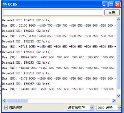
Note: add IRremote folder into installation directory \Arduino\compiler libraries, or it will fail to compile.
For example:C:\Program Files\Arduino\libraries
Not: IRremote klasörünü \Arduino\compiler kütüphanelerinin kurulum klasörüne ekleyin, yoksa kodlama başarısız olur.
Örneğin: C:\Program Files\Arduino\library
Project 15: Analog Value Reading / Analog Değer Okuma
Introduction: / Tanıtım
In this experiment, we will begin the learning of analog I/O interfaces. On an Arduino, there are 6 analog interfaces numbered from 0 to 5. These 6 interfaces can also be used as digital ones numbered as 14-19. After a brief introduction, let's begin our project. Potentiometer used here is a typical output component of analog value that is familiar to us.
Bu deneyde, analog I / O arayüzleri öğrenmeye başlayacağız. Bir Arduino'da, 0'dan 5'e kadar numaralandırılmış 6 analog arabirim vardır. Bu 6 arabirim, 14-19 olarak numaralandırabileceğimiz dijital arayüzler olarak da kullanılabilir. Bu kısa girişten sonra, hadi projemize başlayalım. Burada kullanılan potansiyometre, bize tanıdık olan tipik bir analog değer çıkış bileşenidir.
Hardware Required: / Gerekli Donanım
1.Potentiometer *1
2.Breadboard*1
3.Breadboard jumper wires * several
1.Potansiyometre * 1
2.Breadboard * 1
3.Breadboard jumper kablo * birkaç adet
Connection: / Bağlantı
In this experiment, we will convert the resistance value of the potentiometer to analog ones and display it on the screen. This is an application you need to master well for our future experiments.
Connection circuit as below:
Bu deneyde, potansiyometrenin direnç değerini analog değere dönüştürüp ekranda görüntüleyeceğiz. Bu, gelecekteki deneylerimiz için iyi bir şekilde ustalaşmanız gereken bir uygulamadır.
Bağlantı devresi aşağıdaki gibi :
Connection for UNO R3: / UNO R3 Bağlantısı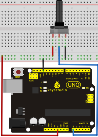
The analog interface we use here is interface A0.
Burada kullandığımız analog arayüz A0'dır.
Sample Code: / Örnek Kod
The program compiling is simple. An analogRead () Statement can read the value of the interface. The A/D acquisition of Arduino 328 is in 10 bits, so the value it reads is among 0 to 1023. One difficulty in this project is to display the value on the screen, which is actually easy to learn. First, we need to set the baud rate in voidsetup (). Displaying the value is a communication between Arduino and PC, so the baud rate of the Arduino should match the the one in the PC's software set up. Otherwise, the display will be messy codes or no display at all. In the lower right corner of the Arduino software monitor window, there is a button for baud rate set up. The set up here needs to match the one in the program. The statement in the program is Serial.begin(); enclosed is the baud rate value, followed by statement for displaying. You can either use Serial.print() or Serial.println() statement.
Programın derlenmesi basittir. Bir analogRead () ifadesi ile arayüzün değeri okunabilir. Arduino 328'in A/D (Analog/Dijital) edinimi 10 bittir, bu yüzden okuduğu değer 0 ile 1023 arasındadır. Bu projedeki zorluklardan biri, ekranda öğrenmesi çok kolay olan değeri göstermektir. Öncelikle voidsetup()'ta baud hızını ayarlamamız gerekiyor. Değerin görüntülenmesi, Arduino ve PC arasındaki bir iletişimdir, bu nedenle Arduino'nun baud hızı, PC'nin yazılımındaki ile aynı olmalıdır. Aksi takdirde, ekranda karman çorman kodlar olacak ya da hiç görüntülenmeyecektir. Arduino yazılımı monitör penceresinin sağ alt köşesinde, baud hızı ayarlaması için bir düğme vardır. Buradaki ayarın programdaki ile eşleşmesi gerekir. Programda "Serial.begin ();" ifadesindeki parantezin içeriği baud rate değeri olup, sonrasında görüntüleme ifadesiyle kullanılır; Serial.print () veya Serial.println () ifadesini kullanabilirsiniz.
int potpin=0;// initialize analog pin 0
int ledpin=13;// initialize digital pin 13
int val=0;// define val, assign initial value 0
void setup()
{
pinMode(ledpin,OUTPUT);// set digital pin as "output”
Serial.begin(9600);// set baud rate at 9600

}
void loop()
{
digitalWrite(ledpin,HIGH);// turn on the LED on pin 13
delay(50);// wait for 0.05 second
digitalWrite(ledpin,LOW);// turn off the LED on pin 13
delay(50);// wait for 0.05 second
val=analogRead(potpin);// read the analog value of analog pin 0, and assign it to val
Serial.println(val);// display val’s value
}
Result: / Sonuç
The sample program uses the built-in LED connected to pin 13. Each time the device reads a value, the LED blinks.
Below is the analog value it reads.
Örnek program kodu, pin 13'e bağlı dahili LED'i kullanır. Cihaz bir değer okuduğunda, LED yanıp söner.
Aşağıda okuduğu analog değerdir.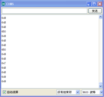
When you rotate the potentiometer knob, you can see the displayed value change. The reading of analog value is a very common function for most sensors output analog value. After calculation, you can get the corresponding value you need.
The experiment is now completed.
Potansiyometre düğmesini çevirdiğinizde, görüntülenen değer değişimini görebilirsiniz. Analog değerin okunması, çoğu sensör çıkışı analog değer olduğu için çok yaygın bir işlevdir. Hesaplamadan sonra ihtiyacınız olan değeri alabilirsiniz.
Deney şimdilik tamamlandı.
Project 16: 74HC595 / 74HC595 Yonga
Introduction: / Tanıtım
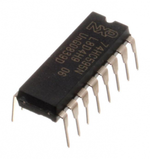
To put it simply, 74HC595 is a combination of 8-digit shifting register, memorizer and equipped with tri-state output. Here, we use it to control 8 LEDs. You may wonder why use a 74HC595 to control LED? Well, think about how many I/O it takes for an Arduino to control 8 LEDs? Yes, 8. For an Arduino 168, it has only 20 I/O including analog ports. To save port resources, we use 74HC595 to reduce the number of ports it needs. Using 74HC595 enables us to use 3 digital I/O port to control 8 LEDs!
Basitçe söylemek gerekirse 74HC595, 8 basamaklı sıralama yazmacı, hafıza ve üç-durumlu çıkış ile donatılmış bir kombinasyondur. Burada, 8 LED'i kontrol etmek için kullanacağız. Peki LED'i kontrol etmek için neden 74HC595 kullanıyoruz? Bir Arduino'nun 8 LED'i kontrol etmesi için kaç I / O (giriş/Çıkış) gerektiğini düşünüyorsunuz? Evet 8. Arduino 168 için, analog portlar dahil sadece 20 I / O vardır. Port kaynaklarını korumak için, ihtiyaç duyduğu port sayısını azaltmak için 74HC595 kullanıyoruz. 74HC595 kullanımı, 8 LED'i kontrol etmek için sadece 3 dijital I / O portu kullanmamızı sağlar!
Hardware Required: / Gerekli Donanım
1.74HC595 chip*1
2.Red M5 LED*4
3.Green M5 LED*4
4.220? resistor*8
5.Breadboard*1
6.Breadboard jumper wires*several
1. 74HC595 yonga * 1
2. Kırmızı M5 LED * 4
3. Yeşil M5 LED * 4
4. 220 Ohm direnç * 8
5. Breadboard * 1
6. Breadbord jumper kablo * birkaç adet
Note: for pin 13 OE port of 74HC595, it should be connected to GND.
Not: 74HC595 yonganın pin 13 OE portu toprağa (GND'ye) bağlanmalıdır.
Connection for UNO R3: / UNO R3 Bağlantısı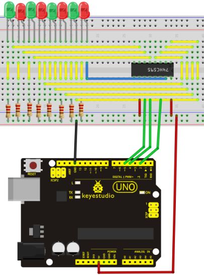
The circuit may seem complicated, but soon you will find it easy!
Devre karmaşık görünebilir, ancak yakında kolay bulacaksınız!
Sample Code: / Örnek Kod
int data = 2;// set pin 14 of 74HC595as data input pin SI
int clock = 5;// set pin 11 of 74hc595 as clock pin SCK
int latch = 4;// set pin 12 of 74hc595 as output latch RCK
int ledState = 0;
const int ON = HIGH;
const int OFF = LOW;
void setup()
{
pinMode(data, OUTPUT);
pinMode(clock, OUTPUT);
pinMode(latch, OUTPUT);
}
void loop()
{
for(int i = 0; i < 256; i++)
{
updateLEDs(i);
delay(500);
}
}
void updateLEDs(int value)
{
digitalWrite(latch, LOW);//
shiftOut(data, clock, MSBFIRST, ~value);// serial data "output”, high level first
digitalWrite(latch, HIGH);// latch
}
Result: / Sonuç
After downloading the program, you can see 8 LEDs display 8-bit binary number.
Programı yükledikten sonra 8 LED'in 8 bitlik ikilik-taban bir sayı gösterdiğini görebilirsiniz.
Project 17: 1-digit LED Segment Display / 1-digit LED Segment Gösterge
Introduction: / Tanıtım
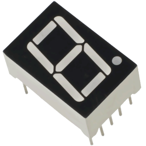
LED segment displays are common for displaying numerical information. It's widely applied on displays of electromagnetic oven, full automatic washing machine, water temperature display, electronic clock, etc. It is necessary for us to learn how it works.
LED segment display is a semiconductor light-emitting device. Its basic unit is a light-emitting diode (LED). LED segment display can be divided into 7-segment display and 8-segment display according to the number of segments. 8-segment display has one more LED unit ( for decimal point display) than 7-segment one. In this experiment, we use a 8-segment display. According to the wiring method of LED units, LED segment displays can be divided into common anode display and common cathode display. Common anode display refers to the one that combine all the anodes of LED units into one common anode (COM).
For the common anode display, connect the common anode (COM) to +5V. When the cathode level of a certain segment is low, the segment is on; when the cathode level of a certain segment is high, the segment is off. For the common cathode display, connect the common cathode (COM) to GND. When the anode level of a certain segment is high, the segment is on; when the anode level of a certain segment is low, the segment is off.
LED segment göstergeleri, sayısal bilgileri görüntülemek için yaygın olarak kullanılır. Yaygın olarak elektromanyetik fırın, tam otomatik çamaşır makinesi, su sıcaklığı göstergesi, elektronik saat vb. göstergelere uygulanır. Nasıl çalıştığını öğrenmemiz gerekir.
LED segment göstergesi yarı iletken ışık yayan bir cihazdır. Temel birimi ışık yayan bir diyottur (LED). LED segment göstergesi, segment sayısına göre 7 segmentli ve 8 segmentli olabilir. 8 segmentli gösterge, 7 segmentli olandan bir fazla LED ünitesine (ondalık nokta gösterimi için) sahiptir. Bu deneyde 8 segmentli bir gösterge kullanıyoruz. LED ünitelerinin kablolama yöntemine göre, LED segment göstergeleri ortak anot göstergesi ve ortak katot göstergesi olarak bölünebilir. Ortak anot göstergesi, LED ünitelerinin tüm anotlarını tek bir ortak anotta (COM) birleştiren gösterge anlamına gelir.
Ortak anot göstergesi için, ortak anotu (COM) +5V'a bağlayın. Belirli bir segmentin katot seviyesi düşük olduğunda, segment açıktır; belirli bir segmentin katot seviyesi yüksek olduğunda, segment kapalıdır. Ortak katot ekranı için ortak katodu (COM) GND'ye bağlayın. Belirli bir segmentin anot seviyesi yüksek olduğunda, segment açıktır; Belirli bir segmentin anot seviyesi düşük olduğunda, segment kapalıdır.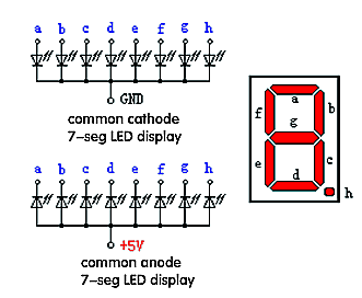
Each segment of the display consists of an LED. So when you use it, you also need to use a current-limiting resistor. Otherwise, LED will be burnt out. In this experiment, we use a common cathode display. As we mentioned above, for common cathode display, connect the common cathode (COM) to GND. When the anode level of a certain segment is high, the segment is on; when the anode level of a certain segment is low, the segment is off.
Ekranın her bölümü bir LED'den oluşur. Bu sebeple kullanırken, akım sınırlayıcı bir direnç de kullanmanız gerekir. Aksi takdirde, LED yanacaktır. Bu deneyde bir ortak katod göstergesi kullanıyoruz. Yukarıda belirttiğimiz gibi, ortak katot gösterimi için, ortak katodu (COM) GND'ye bağlayın. Belirli bir segmentin anot seviyesi yüksek olduğunda, segment açıktır; Belirli bir segmentin anot seviyesi düşük olduğunda, segment kapalıdır.
Hardware Required: / Gerekli Donanım
1. 1-digit LED display*1
2. 220? resistor*8
3. Breadboard*1
4. Breadboard jumper wires*several
1. Bir basamaklı LED gösterge * 1
2. 220 Ohm direnç * 8
3. Breadboard * 1
4. Breadboard jumper kablosu * birkaç adet
Connection: / Bağlantı
Refer to following connection diagram
Connection for UNO R3: / UNO R3 Bağlantısı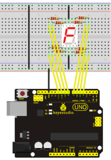
Sample Code:
There are seven segments for numerical display, one for decimal point display. Corresponding segments will be turned on when displaying certain numbers. For example, when displaying number 1, b and c segments will be turned on. We compile a subprogram for each number, and compile the main program to display one number every 2 seconds, cycling display number 0 ~ 9. The displaying time for each number is subject to the delay time, the longer the delay time, the longer the displaying time.
Sayısal gösterim için yedi, ondalık gösterim için bir segment bulunur. Belli sayıları görüntülerken ilgili segmentler açılacaktır. Örneğin, 1 sayısını görüntülerken, b ve c segmentleri açılacaktır. Her sayı için bir alt program derliyoruz ve ana programı 0'dan 9'a kadar olan sayıları her 2 saniyede bir sayı gösterecek şekilde derliyoruz. Her sayının ne kadar süre görüntüleneceği, "delay ()" (uzama) süresine bağladır ve ne kadar uzunsa, gösterim süresi o kadar uzun olur.
// set the IO pin for each segment
int a=7;// set digital pin 7 for segment a
int b=6;// set digital pin 6 for segment b
int c=5;// set digital pin 5 for segment c
int d=10;// set digital pin 10 for segment d
int e=11;// set digital pin 11 for segment e
int f=8;// set digital pin 8 for segment f
int g=9;// set digital pin 9 for segment g
int dp=4;// set digital pin 4 for segment dp
void digital_0(void) // display number 5
{
unsigned char j;
digitalWrite(a,HIGH);
digitalWrite(b,HIGH);
digitalWrite(c,HIGH);
digitalWrite(d,HIGH);
digitalWrite(e,HIGH);
digitalWrite(f,HIGH);
digitalWrite(g,LOW);
digitalWrite(dp,LOW);
}
void digital_1(void) // display number 1
{
unsigned char j;
digitalWrite(c,HIGH);// set level as "high” for pin 5, turn on segment c
digitalWrite(b,HIGH);// turn on segment b
for(j=7;j<=11;j++)// turn off other segments
digitalWrite(j,LOW);
digitalWrite(dp,LOW);// turn off segment dp
}
void digital_2(void) // display number 2
{
unsigned char j;
digitalWrite(b,HIGH);
digitalWrite(a,HIGH);
for(j=9;j<=11;j++)
digitalWrite(j,HIGH);
digitalWrite(dp,LOW);
digitalWrite(c,LOW);
digitalWrite(f,LOW);
}
void digital_3(void) // display number 3
{digitalWrite(g,HIGH);
digitalWrite(a,HIGH);
digitalWrite(b,HIGH);
digitalWrite(c,HIGH);
digitalWrite(d,HIGH);
digitalWrite(dp,LOW);
digitalWrite(f,LOW);
digitalWrite(e,LOW);
}
void digital_4(void) // display number 4
{digitalWrite(c,HIGH);
digitalWrite(b,HIGH);
digitalWrite(f,HIGH);
digitalWrite(g,HIGH);
digitalWrite(dp,LOW);
digitalWrite(a,LOW);
digitalWrite(e,LOW);
digitalWrite(d,LOW);
}
void digital_5(void) // display number 5
{
unsigned char j;
digitalWrite(a,HIGH);
digitalWrite(b, LOW);
digitalWrite(c,HIGH);
digitalWrite(d,HIGH);
digitalWrite(e, LOW);
digitalWrite(f,HIGH);
digitalWrite(g,HIGH);
digitalWrite(dp,LOW);
}
void digital_6(void) // display number 6
{
unsigned char j;
for(j=7;j<=11;j++)
digitalWrite(j,HIGH);
digitalWrite(c,HIGH);
digitalWrite(dp,LOW);
digitalWrite(b,LOW);
}
void digital_7(void) // display number 7
{
unsigned char j;
for(j=5;j<=7;j++)
digitalWrite(j,HIGH);
digitalWrite(dp,LOW);
for(j=8;j<=11;j++)
digitalWrite(j,LOW);
}
void digital_8(void) // display number 8
{
unsigned char j;
for(j=5;j<=11;j++)
digitalWrite(j,HIGH);
digitalWrite(dp,LOW);
}
void digital_9(void) // display number 5
{
unsigned char j;
digitalWrite(a,HIGH);
digitalWrite(b,HIGH);
digitalWrite(c,HIGH);
digitalWrite(d,HIGH);
digitalWrite(e, LOW);
digitalWrite(f,HIGH);
digitalWrite(g,HIGH);
digitalWrite(dp,LOW);
}
void setup()
{
int i;// set variable
for(i=4;i<=11;i++)
pinMode(i,OUTPUT);// set pin 4-11as "output”
}
void loop()
{
while(1)
{
digital_0();// display number 0
delay(1000);// wait for 1s
digital_1();// display number 1
delay(1000);// wait for 1s
digital_2();// display number 2
delay(1000); // wait for 1s
digital_3();// display number 3
delay(1000); // wait for 1s
digital_4();// display number 4
delay(1000); // wait for 1s
digital_5();// display number 5
delay(1000); // wait for 1s
digital_6();// display number 6
delay(1000); // wait for 1s
digital_7();// display number 7
delay(1000); // wait for 1s
digital_8();// display number 8
delay(1000); // wait for 1s
digital_9();// display number 9
delay(1000); // wait for 1s
}
}
Result: / Sonuç
LED segment display will display the number from 0 to 9.
LED segment göstergesi, 0 ~ 9 arasındaki sayıları gösterecektir.
Project 18: 4-digit LED Segment Display / 4-basamak LED Segment Gösterge
Introduction: / Tanıtım
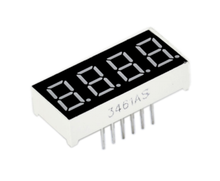
In this experiment, we use an Arduino to drive a common anode, 4-digit, 7-segment LED display. For LED display, current-limiting resistors are indispensable. There are two wiring method for Current-limiting resistor. One is to connect one resistor for each anode, 4 in total for d1-d4 anode. An advantage for this method is that it requires fewer resistors, only 4. But it cannot maintain consistent brightness, 1 the brightest, 8, the least bright. Another method is to connect one resistor to each pin. It guarantees consistent brightness, but requires more resistors. In this experiment, we use 8 220? resistors (we use 220? resistors because no 100? resistor available. If you use 100?, the displaying is more brighter).
Bu deneyde, Arduino ile ortak anot, 4 basamaklı, 7 segment LED göstergesi kullanıyoruz. LED göstergede akım sınırlayıcı dirençler vazgeçilmezdir. Akım sınırlama direnci için iki kablolama yöntemi vardır. Biri, her bir anot için bir direnç, d1-d4 anotu için toplam 4 adet bağlamaktır. Bu yöntemin bir avantajı, sadece 4 direnç gerektirmesidir. Ancak tutarlı parlaklık alamazsınız, 1 en parlak görünürken, 8 en az parlaklığa sahip olacaktır. Diğer bir yöntem, her bir pine bir direnç bağlamaktır. Tutarlı parlaklığı garanti eder, ancak daha fazla direnç gerektirir. Bu deneyde 8 adet 220ohm direnç kullanacağız. (220 ohm direnç kullanıyoruz çünkü 100 ohm direnç setimizde mevcut değil. 100 ohm kullanmamız durumunda görüntüleme daha parlak olacaktır.)
Connection: / Bağlantı
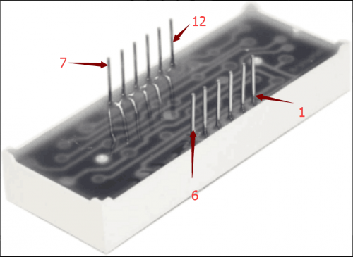
For 4-digit displays, there are 12 pins in total. When you place the decimal point downward (see below photo position), the pin on the lower left part is refer to as 1, the upper left part 12.
4 basamaklı göstergeler için toplamda 12 ayak vardır. Sol alt kısımdaki pin 1, sol üst kısımdaki pin 12 olarak belirtilir. (aşağıdaki görsellere bakın)
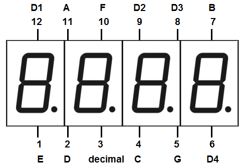
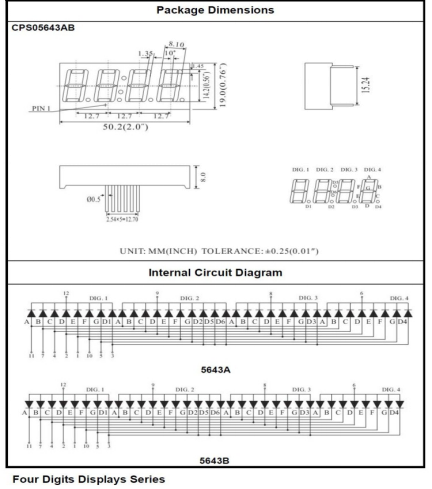
Manual for LED segment display:
LED segment göstergesi için kılavuz:
Connection for UNO R3: / UNO R3 Bağlantısı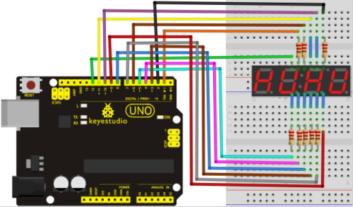
Sample Code: / Örnek Kod
// display 1234
	// select pin for cathode
	int a = 1;
	int b = 2;
	int c = 3;
	int d = 4;
	int e = 5;
	int f = 6;
	int g = 7;
	int dp = 8;
	// select pin for anode
	int d4 = 9;
	int d3 = 10;
	int d2 = 11;
	int d1 = 12;
	// set variable
	long n = 1230;
	int x = 100;
	int del = 55;  // fine adjustment for clock

	void setup()
	{
	  pinMode(d1, OUTPUT);
	  pinMode(d2, OUTPUT);
	  pinMode(d3, OUTPUT);
	  pinMode(d4, OUTPUT);
	  pinMode(a, OUTPUT);
	  pinMode(b, OUTPUT);
	  pinMode(c, OUTPUT);
	  pinMode(d, OUTPUT);
	  pinMode(e, OUTPUT);
	  pinMode(f, OUTPUT);
	  pinMode(g, OUTPUT);
	  pinMode(dp, OUTPUT);
	}
/////////////////////////////////////////////////////////////
void loop()

{
 Display(1, 1);
 Display(2, 2);
 Display(3, 3);
 Display(4, 4);

}
///////////////////////////////////////////////////////////////
void WeiXuan(unsigned char n)//
{
    switch(n)
     {
	case 1:
	  digitalWrite(d1,LOW);
 	  digitalWrite(d2, HIGH);
	  digitalWrite(d3, HIGH);
	  digitalWrite(d4, HIGH);
	 break;
	 case 2:
	  digitalWrite(d1, HIGH);
 	  digitalWrite(d2, LOW);
	  digitalWrite(d3, HIGH);
	  digitalWrite(d4, HIGH);
	    break;
	  case 3:
	    digitalWrite(d1,HIGH);
 	   digitalWrite(d2, HIGH);
	   digitalWrite(d3, LOW);
	   digitalWrite(d4, HIGH);
	    break;
	  case 4:
	   digitalWrite(d1, HIGH);
 	   digitalWrite(d2, HIGH);
	   digitalWrite(d3, HIGH);
	   digitalWrite(d4, LOW);
	    break;
        default :
           digitalWrite(d1, HIGH);
	   digitalWrite(d2, HIGH);
	   digitalWrite(d3, HIGH);

	   digitalWrite(d4, HIGH);
        break;
	  }
}
void Num_0()
{
  digitalWrite(a, HIGH);
  digitalWrite(b, HIGH);
  digitalWrite(c, HIGH);
  digitalWrite(d, HIGH);
  digitalWrite(e, HIGH);
  digitalWrite(f, HIGH);
  digitalWrite(g, LOW);
  digitalWrite(dp,LOW);
}
void Num_1()
{
  digitalWrite(a, LOW);
  digitalWrite(b, HIGH);
  digitalWrite(c, HIGH);
  digitalWrite(d, LOW);
  digitalWrite(e, LOW);
  digitalWrite(f, LOW);
  digitalWrite(g, LOW);
  digitalWrite(dp,LOW);
}
void Num_2()
{
  digitalWrite(a, HIGH);
  digitalWrite(b, HIGH);
  digitalWrite(c, LOW);
  digitalWrite(d, HIGH);
  digitalWrite(e, HIGH);
  digitalWrite(f, LOW);
  digitalWrite(g, HIGH);
  digitalWrite(dp,LOW);
}
void Num_3()
{
  digitalWrite(a, HIGH);

  digitalWrite(b, HIGH);
  digitalWrite(c, HIGH);
  digitalWrite(d, HIGH);
  digitalWrite(e, LOW);
  digitalWrite(f, LOW);
  digitalWrite(g, HIGH);
  digitalWrite(dp,LOW);
}
void Num_4()
{
  digitalWrite(a, LOW);
  digitalWrite(b, HIGH);
  digitalWrite(c, HIGH);
  digitalWrite(d, LOW);
  digitalWrite(e, LOW);
  digitalWrite(f, HIGH);
  digitalWrite(g, HIGH);
  digitalWrite(dp,LOW);
}
void Num_5()
{
  digitalWrite(a, HIGH);
  digitalWrite(b, LOW);
  digitalWrite(c, HIGH);
  digitalWrite(d, HIGH);
  digitalWrite(e, LOW);
  digitalWrite(f, HIGH);
  digitalWrite(g, HIGH);
  digitalWrite(dp,LOW);
}
void Num_6()
{
  digitalWrite(a, HIGH);
  digitalWrite(b, LOW);
  digitalWrite(c, HIGH);
  digitalWrite(d, HIGH);
  digitalWrite(e, HIGH);
  digitalWrite(f, HIGH);
  digitalWrite(g, HIGH);
  digitalWrite(dp,LOW);

}
void Num_7()
{
  digitalWrite(a, HIGH);
  digitalWrite(b, HIGH);
  digitalWrite(c, HIGH);
  digitalWrite(d, LOW);
  digitalWrite(e, LOW);
  digitalWrite(f, LOW);
  digitalWrite(g, LOW);
  digitalWrite(dp,LOW);
}
void Num_8()
{
  digitalWrite(a, HIGH);
  digitalWrite(b, HIGH);
  digitalWrite(c, HIGH);
  digitalWrite(d, HIGH);
  digitalWrite(e, HIGH);
  digitalWrite(f, HIGH);
  digitalWrite(g, HIGH);
  digitalWrite(dp,LOW);
}
void Num_9()
{
  digitalWrite(a, HIGH);
  digitalWrite(b, HIGH);
  digitalWrite(c, HIGH);
  digitalWrite(d, HIGH);
  digitalWrite(e, LOW);
  digitalWrite(f, HIGH);
  digitalWrite(g, HIGH);
  digitalWrite(dp,LOW);
}
void Clear()  // clear the screen
{
  digitalWrite(a, LOW);
  digitalWrite(b, LOW);
  digitalWrite(c, LOW);
  digitalWrite(d, LOW);

  digitalWrite(e, LOW);
  digitalWrite(f, LOW);
  digitalWrite(g, LOW);
  digitalWrite(dp,LOW);
}
void pickNumber(unsigned char n)// select number
{
  switch(n)
  {
   case 0:Num_0();
   break;
   case 1:Num_1();
   break;
   case 2:Num_2();
   break;
   case 3:Num_3();
   break;
   case 4:Num_4();
   break;
   case 5:Num_5();
   break;
   case 6:Num_6();
   break;
   case 7:Num_7();
   break;
   case 8:Num_8();
   break;
   case 9:Num_9();
   break;
   default:Clear();
   break;
  }
}
void Display(unsigned char x, unsigned char Number)//  take x as coordinate and display number
{
  WeiXuan(x);
  pickNumber(Number);
 delay(1);
 Clear() ; // clear the screen
}
Result: / Sonuç
Download the above code to the controller board and see the result.
It will display the number 1234.
Note: if it’s not displaying correctly, check the wiring.
Yukarıdaki kodu denetleyici karta yükleyin ve sonucu görün.
1234 sayısını gösterecektir.
Not: doğru görüntülenmiyorsa, kabloları kontrol edin.
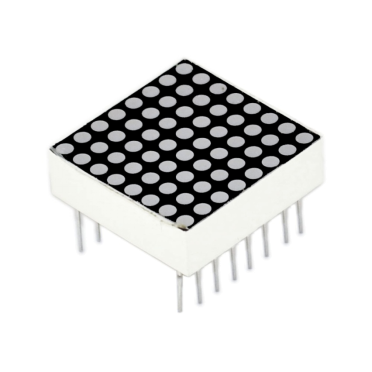
Project 19: 8*8 LED Matrix / 8*8 LED Matriks
Introduction: / Tanıtım
With low-voltage scanning, LED dot-matrix display have some advantages such as power saving, long service life, low cost, high brightness, wide angle of view, long visual range, waterproof, and numerous specifications. LED dot-matrix display can meet the needs of different applications, thus have a broad development prospect. This time, we will conduct an LED dot-matrix experiment to experience its charm firsthand.
Düşük voltaj taramalı LED Dot-matrix (nokta-matris) ekran; güç tasarrufu, uzun servis ömrü, düşük maliyet, yüksek parlaklık, geniş görüş açısı, uzun görüş mesafesi, su geçirmezlik gibi çok sayıda avantajlı özelliklere sahiptir. LED dot-matrix ekran, farklı uygulamaların ihtiyaçlarını karşılayabilir, böylece geniş bir geliştirme alanına sahiptir. Şimdi, çekiciliğini ilk elden deneyimlemek için bir LED dot-matrix deneyi yapacağız.
Hardware Required: / Gerekli Donanım
- 1 * Uno board
- 1 * 8*8 dot-matrix
- 8 * Resistor (220?)
- 1 * Breadboard
- 1 * USB cable
- Jumper wires
- 1 * UNO denetleyici kart
- 1 * 8x8 Dot-matrix
- 8 * Direnç (220 ohm)
- 1 * Breadboard
- 1 * USB kablosu
- Jumper kablolar
Connection: / Bağlantı
The external view of a dot-matrix is shown as follows:
Dot-matrix birimin dış görünümü şu şekildedir:
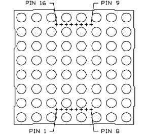
The display principle of the 8*8 dot-matrix: / Çalışma prensibi:
The 8*8 dot-matrix is made up of sixty-four LEDs, and each LED is placed at the cross point of a row and a column. When the electrical level of a certain row is 1 and the electrical level of a certain column is 0, the corresponding LED will be on. If you want to light the LED on the first dot, you should set pin 9 to high level and pin 13 to low level. If you want to light LEDs on the first row, you should set pin 9 to high level and pins 13, 3, 4, 10, 6, 11, 15 and 16 to low level. If you want to light the LEDs on the first column, set pin 13 to low level and pins 9, 14, 8, 12, 1, 7, 2 and 5 to high level.
8 * 8 Dot-matrix altmış dört LED'den oluşur ve her bir LED bir satır ve bir sütunun kesişiminde yerleşiktir. Belirli bir sıranın elektrik seviyesi 1 ve belirli bir sütunun elektrik seviyesi 0 olduğunda, ilgili LED yanacaktır. Eğer ilk LED'i yakmak istiyorsanız, pin 9'a yüksek seviyeye ve pin 13'e düşük seviye vermelisiniz. İlk sıradaki LED'leri yakmak istiyorsanız, 9 numaralı pini yüksek seviyeye, 13, 3, 4, 10, 6, 11, 15 ve 16 numaralı pinleri düşük seviyeye getirmelisiniz. LED'leri ilk sütunda yakmak istiyorsanız, 13 numaralı pini düşük seviyeye ve 9, 14, 8, 12, 1, 7, 2, 5 numaralı pinleri yüksek seviyeye ayarlayın.
The internal view of a dot-matrix is shown as follows:
Bir nokta matrisin iç görünümü aşağıdaki gibi gösterilmiştir:
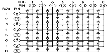
The principle of 74HC595 has been previously illustrated. One chip is used to control the rows of the dot-matrix while the other chip is used to control the columns.
74HC595 yongasının çalışma ilkesi daha önce açıklanmıştı. Bir yonga, Dot-matrix satırlarını kontrol ederken, diğer yonga sütunlarını kontrol etmek için kullanılır.
Connect circuit as shown in the following diagram:
Devreyi aşağıdaki şemada gösterildiği gibi bağlayın:
Connection for UNO R3: / UNO R3 Bağlantısı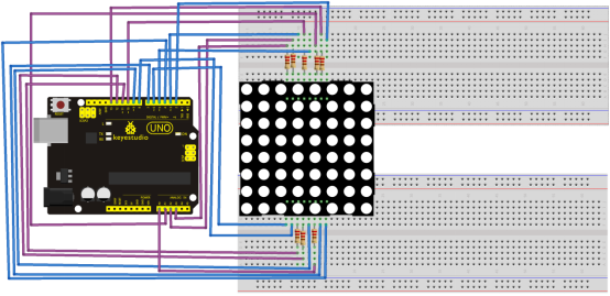
Sample Code for Displaying "0”: / "0" Rakamı Göstermek için Örnek Kod
// set an array to store character of "0”
unsigned char Text[]={0x00,0x1c,0x22,0x22,0x22,0x22,0x22,0x1c};
void Draw_point(unsigned char x,unsigned char y)// point drawing function
{ clear_();
   digitalWrite(x+2, HIGH);
   digitalWrite(y+10, LOW);
   delay(1);
}
void show_num(void)// display function, call point drawing function
{
  unsigned char i,j,data;
  for(i=0;i<8;i++)
  {
    data=Text[i];
    for(j=0;j<8;j++)
    {
      if(data & 0x01)Draw_point(j,i);
      data>>=1;

    }
  }
}
void setup(){
int i = 0 ;
for(i=2;i<18;i++)
 {
   pinMode(i, OUTPUT);
  }
  clear_();
}
void loop()
{ show_num();
}
void clear_(void)// clear screen
{for(int i=2;i<10;i++)
  digitalWrite(i, LOW);
  for(int i=0;i<8;i++)
  digitalWrite(i+10, HIGH);
}
Result: / Sonuç
Burn the program into Uno board, the dot-matrix will display 0.
Programı Uno karta yükleyin, nokta-matris 0 gösterecektir.
Project 20: 1602 LCD / 1602 LCD
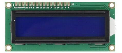
Introduction: / Tanıtım
In this experiment, we use an Arduino to drive the 1602 LCD.
1602 LCD has wide applications. In the beginning,1602 LCD uses a HD44780 controller. Now, almost all 1602 LCD module uses a compatible IC, but their features are basically the same.
Bu deneyde, 1602 LCD'yi çalıştırmak için bir Arduino kullanıyoruz.
1602 LCD geniş uygulamalara sahiptir. Başlangıçta, 1602 LCD bir HD44780 denetleyicisi kullanıyordu. Şimdi, hemen hemen tüm 1602 LCD modülleri uyumlu bir IC (Integrated Circuit), yani entegre devre kullanıyor, ancak özellikleri temel olarak aynı.
1602LCD Parameters: / 1602LCD Parametreler
- Display Capacity: 16 × 2 characters.
- Chip Operating Voltage: 4.5 ~ 5.5V.
- Working Current: 2.0mA (5.0V).
- Optimum working voltage of the module is 5.0V.
- Character Size: 2.95 * 4.35 (W * H) mm.
- Ekran Kapasitesi: 16 × 2 karakter
- Çip Çalışma Gerilimi: 4.5 ~ 5.5V
- Çalışma Akımı: 2.0mA (5.0V)
- Modülün optimum çalışma voltajı 5,0V'tur
- Karakter Boyutu: 2.95 * 4.35 (G * Y) mm
Pin Description of 1602 LCD: / 1602LCD için Pin Açıklamaları
| No. | Mark | Pin Description | No. | Mark | Pin Description |
|---|---|---|---|---|---|
| 1 | VSS | Power GND | 9 | D2 | Date I/O |
| 2 | VDD | Power Positive | 10 | D3 | Date I/O |
| 3 | VL | LCD Voltage Bias Signal | 11 | D4 | Date I/O |
| 4 | RS | Select data/command(V/L) | 12 | D5 | Date I/O |
| 5 | R/W | Select read/write(H/L) | 13 | D6 | Date I/O |
| 6 | E | Enable Signal | 14 | D7 | Date I/O |
| 7 | D0 | Date I/O | 15 | BLA | Back Light Power Positive |
| 8 | D1 | Date I/O | 16 | BLK | Back Light Power Negative |
Interface Description: / Arayüz Açıklaması
1. two power sources, one for module power, another one for backlight, generally use 5V. In this project, we use 3.3V for backlight.
2. VL is the pin for adjusting contrast ratio; it usually connects a potentiometer(no more than 5 Kohm) in series for its adjustment. In this experiment, we use a 1K? resistor. For the connection, it has 2 methods, namely high potential and low potential. Here, we use low potential method; connect the resistor and then the GND.
3. RS is a very common pin in LCD. It's a selecting pin for command/data. When the pin is in high level, it's in data mode; when it's in low level, it's in command mode.
4. RW pin is also very common in LCD. It's a selecting pin for read/write. When the pin is in high level, it's in read operation; when it's in low level, it's in write operation.
5. E pin is also very common in LCD. Usually, when the signal in the bus is stabilized, it sends out a positive pulse requiring read operation. When this pin is in high level, the bus is not allowed to have any change.
6. D0-D7 is 8-bit bidirectional parallel bus, used for command and data transmission.
7. BLA is anode for back light; BLK, cathode for back light.
1. Biri modül gücü, diğeri arka ışık için olmak üzere İki güç kaynağı, genellikle 5V kullanır. Bu projede, arka ışık için 3.3V kullanıyoruz.
2. VL, kontrast oranını ayarlamak için kullanılan pindir; genellikle ayar için seri olarak bir potansiyometreye (en fazla 5 Kohm) bağlanır. Bu deneyde 1 Kohm dirençli kullanacağız. Bağlantı için, yüksek potansiyel ve düşük potansiyel olmak üzere 2 yöntem vardır. Burada düşük potansiyel yöntemi kullanacağız; direnç ve ardından GND'yi bağlayın.
3. RS, LCD'de çok yaygın bir pindir. Komut veya veri için seçim pini. Pin yüksek seviyede olduğunda veri modundadır, düşük seviyedeyken komut modundadır.
4. RW pini de LCD'de çok yaygındır. Okuma/yazma için seçmeli bir pindir. Pi yüksek seviyedeyken okuma modundadır, düşük seviyedeyken yazma modunda.
5. LCD'de E pini de çok yaygındır. Genellikle veriyolu içindeki sinyal stabilize olduğunda, okuma işlemi için pozitif bir sinyal gönderir. Bu pin yüksek seviyedeyken, veriyolunda herhangi bir değişikliğe izin verilmez.
6. D0-D7, komut ve veri iletimi için kullanılan 8 bit çift yönlü paralel veriyoludur.
7. BLA, arka ışık için anoddur. BLK ise arka ışık için katot.
4 Basic Operations of 1602LCD:
| Read status / Durum okuma | input / giriş | RS=L, R/W=H, E=H | output / çıkış | D0-D7=status word |
| Write command / Komut yazma | input / giriş | RS=L, R/W=H, D0-D7=command code (Komut kodu), E=high pulse (Yüksek Sinyal) | output / çıkış | none / yok |
| Read data / Veri okuma | input / giriş | RS=H, R/W=H, E=H | output / çıkış | D0-D7=data (Veri) |
| Write data / Veri yazma | input / giriş | RS=H, R/W=L, D0-D7=data, E=high pulse (Yüksek Sinyal) | output / çıkış | none / yok |
H yüksek, L düşük sinyal
Hardware Required: / Gerekli Donanım
- 1 * Controller Board
- 1 * 1602 LCD
- 1 * Potentiometer
- 1 * Breadboard
- 1 * USB Cable
- Jumper Wires
- 1 * Denetleyici Kart
- 1 * 1602 LCD
- 1 * Potansiyometre
- 1 * Breadboard
- 1 * USB Kablosu
- Jumper kabloları
Connection & Sample Program: / Bağlantı ve Örnek Program
1602 can directly communicate with Arduino. According to the product manual, it has two connection methods, namely 8-bit connection and 4-bit connection.
1602 doğrudan Arduino ile iletişim kurabilir. Ürün kılavuzuna göre, 8-bit bağlantı ve 4-bit bağlantı olmak üzere iki bağlantı yöntemi vardır.
8-bit connection method: / 8-bit Bağlantı Yöntemi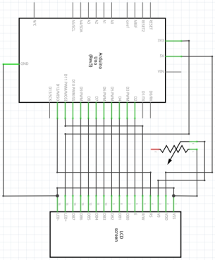
Connection for UNO R3: / UNO R3 Bağlantısı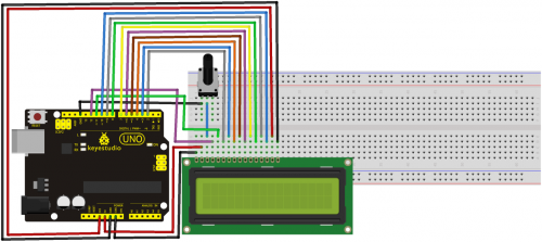
Sample Code A: / Örnek Kod A
int DI = 12;
int RW = 11;
int DB[] = {3, 4, 5, 6, 7, 8, 9, 10};// use array to select pin for bus
int Enable = 2;

void LcdCommandWrite(int value) {
// define all pins
int i = 0;
for (i=DB[0]; i <= DI; i++) // assign value for bus
{
   digitalWrite(i,value & 01);// for 1602 LCD, it uses D7-D0( not D0-D7) for signal identification; here, it’s used for signal inversion.
   value >>= 1;
}
digitalWrite(Enable,LOW);
delayMicroseconds(1);
digitalWrite(Enable,HIGH);
delayMicroseconds(1);  // wait for 1ms
digitalWrite(Enable,LOW);
delayMicroseconds(1);  // wait for 1ms
}

void LcdDataWrite(int value) {
// initialize all pins
int i = 0;
digitalWrite(DI, HIGH);
digitalWrite(RW, LOW);
for (i=DB[0]; i <= DB[7]; i++) {
   digitalWrite(i,value & 01);
   value >>= 1;
}
digitalWrite(Enable,LOW);
delayMicroseconds(1);
digitalWrite(Enable,HIGH);
delayMicroseconds(1);
digitalWrite(Enable,LOW);
delayMicroseconds(1);  // wait for 1ms
}

void setup (void) {
int i = 0;
for (i=Enable; i <= DI; i++) {
   pinMode(i,OUTPUT);
}
delay(100);
// initialize LCD after a brief pause
// for LCD control
LcdCommandWrite(0x38);  // select as 8-bit interface, 2-line display, 5x7 character size
delay(64);
LcdCommandWrite(0x38);  // select as 8-bit interface, 2-line display, 5x7 character size
delay(50);
LcdCommandWrite(0x38);  // select as 8-bit interface, 2-line display, 5x7 character size
delay(20);
LcdCommandWrite(0x06);  // set input mode
                         // auto-increment, no display of shifting
delay(20);
LcdCommandWrite(0x0E);  // display setup
                         // turn on the monitor, cursor on, no flickering
delay(20);
LcdCommandWrite(0x01);  // clear the scree, cursor position returns to 0
delay(100);
LcdCommandWrite(0x80);  //  display setup
                         //  turn on the monitor, cursor on, no flickering

delay(20);
}

void loop (void) {
  LcdCommandWrite(0x01);  // clear the scree, cursor position returns to 0
  delay(10);
  LcdCommandWrite(0x80+3);
  delay(10);
  // write in welcome message
  LcdDataWrite('W');
  LcdDataWrite('e');
  LcdDataWrite('l');
  LcdDataWrite('c');
  LcdDataWrite('o');
  LcdDataWrite('m');

  LcdDataWrite('e');
  LcdDataWrite(' ');
  LcdDataWrite('t');
  LcdDataWrite('o');
  delay(10);
  LcdCommandWrite(0xc0+1);  // set cursor position at second line, second position
  delay(10);
  LcdDataWrite('g');
  LcdDataWrite('e');
  LcdDataWrite('e');
  LcdDataWrite('k');
  LcdDataWrite('-');
  LcdDataWrite('w');
  LcdDataWrite('o');
  LcdDataWrite('r');
  LcdDataWrite('k');
  LcdDataWrite('s');
  LcdDataWrite('h');
  LcdDataWrite('o');
  LcdDataWrite('p');
  delay(5000);
  LcdCommandWrite(0x01);  // clear the screen, cursor returns to 0
  delay(10);
  LcdDataWrite('I');
  LcdDataWrite(' ');
  LcdDataWrite('a');
  LcdDataWrite('m');
  LcdDataWrite(' ');
  LcdDataWrite('h');
  LcdDataWrite('o');
  LcdDataWrite('n');
  LcdDataWrite('g');
  LcdDataWrite('y');
  LcdDataWrite('i');
  delay(3000);
  LcdCommandWrite(0x02); // set mode as new characters replay old ones, where there is no new ones remain the same
  delay(10);
  LcdCommandWrite(0x80+5); // set cursor position at first line, sixth position
  delay(10);

  LcdDataWrite('t');
  LcdDataWrite('h');
  LcdDataWrite('e');
  LcdDataWrite(' ');
  LcdDataWrite('a');
  LcdDataWrite('d');
  LcdDataWrite('m');
  LcdDataWrite('i');
  LcdDataWrite('n');
  delay(5000);
}
4-bit connection method: / 4-bit Bağlantı Yöntemi
When using this module, 8-bit connection uses all the digital pins of the Arduino, leaving no pin for sensors. What then? you can use 4-bit connection.
Connection Circuit: / Devre Bağlantısı
Connection for UNO R3: / UNO R3 Bağlantısı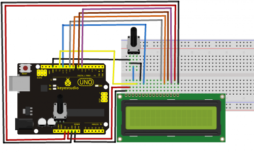
After the connection, upload below code to the controller board and see how it goes.
Bağlantıdan sonra, aşağıdaki kodu kontrol panosuna yükleyin ve nasıl gittiğini görün.
Sample Code B: / Örnek Kod B
/* LiquidCrystal Library - Hello World Demonstrates the use a 16x2 LCD display. The LiquidCrystal library works with all LCD displays that are compatible with the Hitachi HD44780 driver. There are many of them out there, and you can usually tell them by the 16-pin interface. This sketch prints "Hello World!" to the LCD and shows the time. The circuit: * LCD RS pin to digital pin 12 * LCD Enable pin to digital pin 11 * LCD D4 pin to digital pin 9 * LCD D5 pin to digital pin 8 * LCD D6 pin to digital pin 7 * LCD D7 pin to digital pin 6 * LCD R/W pin to ground * LCD VSS pin to ground * LCD VCC pin to 5V * 10K resistor: * ends to +5V and ground * wiper to LCD VO pin (pin 3) Library originally added 18 Apr 2008 by David A. Mellis library modified 5 Jul 2009 by Limor Fried (http://www.ladyada.net) example added 9 Jul 2009 by Tom Igoe modified 22 Nov 2010 by Tom Igoe This example code is in the public domain. http://www.arduino.cc/en/Tutorial/LiquidCrystal */ // include the library code: #include// initialize the library with the numbers of the interface pins LiquidCrystal lcd(12, 11, 9, 8, 7, 6); void setup() { // set up the LCD's number of columns and rows: lcd.begin(16, 2); // Print a message to the LCD. lcd.print("hello, world!"); } void loop() { // set the cursor to column 0, line 1 // (note: line 1 is the second row, since counting begins with 0): lcd.setCursor(0, 1); // print the number of seconds since reset: lcd.print(millis() / 1000); }
Project 21: 9g Servo Control / 9g Servo Motor Kontrolü
Introduction: / Tanıtım
Servomotor is a position control rotary actuator. It mainly consists of housing, circuit board, core-less motor, gear and position sensor. The receiver or MCU outputs a signal to the servomotor. The motor has a built-in reference circuit that gives out reference signal, cycle of 20ms and width of 1.5ms. The motor compares the acquired DC bias voltage to the voltage of the potentiometer and outputs a voltage difference. The IC on the circuit board will decide the rotate direction accordingly and drive the core-less motor. The gear then pass the force to the shaft. The sensor will determine whether it has reached the commanded position according to the feedback signal. Servomotors are used in control systems that require to have and maintain different angles. When the motor speed is definite, the gear will cause the potentiometer to rotate. When the voltage difference reduces to zero, the motor stops. Normally, the rotation angle range is among 0-180 degrees.
Servo motor, pozisyon kontrolü için bir döndürme birimidir. Yapı olarak devre kartı, çekirdeksiz motor, dişli ve konum sensöründen oluşur. Alıcı veya MCU, servo motora bir sinyal verir. Motor, 20ms'lik döngülerle 1.5ms'lik genişlikte referans sinyali veren dahili bir referans devresine sahiptir. Motor, elde ettiği DC voltajını, potansiyometrenin voltajıyla karşılaştırır ve voltaj farkı verir. Devre kartındaki IC (entegre devre), buna göre dönüş yönüne karar verecek ve çekirdeksiz motoru çalıştıracaktır. Dişli daha sonra kuvveti mile iletir. Sensör, geri besleme sinyaline göre komut verilen konuma ulaşılıp ulaşılmadığını belirleyecektir. Servomotorlar, farklı açıları olan ve açı devamı gerektiren kontrol sistemlerinde kullanılır. Motor hızı belli olduğunda, dişli potansiyometrenin dönmesine neden olur. Gerilim farkı sıfıra düştüğünde, motor durur. Normal olarak, dönme açısı aralığı 0-180 derece arasındadır.
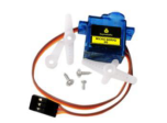
Servomotor comes with many specifications. But all of them have three connection wires, distinguished by brown, red, orange(different brand may have different colors. Brown one is for GND, red one for power positive, orange one for signal line.
Servomotor birçok özellikle birlikte gelir. Ancak hepsinde kahverengi, kırmızı, turuncu ile ayırt edilen üç bağlantı kablosu vardır (farklı markalar farklı renklere sahip olabilir). Kahverengi olan GND için, kırmızı olan pozitif güç için, turuncu olan sinyal hattı (PWM) için.
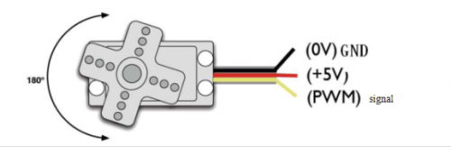
The rotate angle of the servo motor is controlled by regulating the duty cycle of the PWM(Pulse-Width Modulation) signal. The standard cycle of the PWM signal is 20ms(50Hz). Theoretically, the width is distributed between 1ms-2ms, but in fact, it's between 0.5ms-2.5ms. The width corresponds the rotate angle from 0° to 180°. But note that for different brand motor, the same signal may have different rotating angles.
Servo motorun dönme açısı, PWM (Darbe-Genişlik Modülasyonu) sinyalinin görev döngüsü düzenlenerek kontrol edilir. PWM sinyalinin standart döngüsü 20ms'dir (50Hz). Teorik olarak, genişlik 1ms-2ms arasındadır, ancak gerçekte 0.5ms-2.5ms arasındadır. Genişlik, dönme açısında 0° ile 180° arasındadır. Ancak farklı marka motorlar için aynı sinyalin farklı dönüş açıları olabileceğini unutmayın.
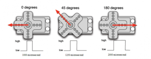
With some basic knowledge, let's learn how to control a servomotor. In this experiment, you only need a servomotor and several jumper wires.
Bu temel bilgilerle, bir servo motoru nasıl kontrol edeceğimizi öğrenelim. Bu deneyde, sadece bir servo motora ve birkaç jumper (aktarma) kablosuna ihtiyacınız var.
Hardware Required: / Gerekli donanım
- RB—412 servomotor*1
- Breadboard jumper wire*several
- RB—412 servomotor * 1
- Breadboard jumper kablo * birkaç adet
Connection & Sample Program: / Bağlantı ve Örnek program
There are two ways to control a servomotor with Arduino. One is to use a common digital port of Arduino to produce square wave with different duty cycle to simulate PWM signal, and then use that signal to control the positioning of the motor. Another way is to directly use the Servo function of the Arduino to control the motor. In this way, the program will be more easier but it can only control two-contact motor for the servo function, only digital pin 9 and 10 is available. The Arduino drive capacity is limited. So if you need to control more than one motor, you will need external power.
Arduino ile bir servo motoru kontrol etmenin iki yolu vardır. Bunlardan biri, PWM sinyalini simüle etmek üzere, farklı görev döngüsüne sahip kare dalga üretmek için ortak bir Arduino dijital bağlantı noktasını kullanmak ve ardından motorun konumunu bu sinyalle kontrol etmektir. Başka bir yol ise, motoru kontrol etmek için Arduino'nun Servo işlevini doğrudan kullanmaktır. Bu şekilde, program daha kolay olur ancak servo fonksiyonu için sadece iki kontak motoru kontrol edebilir ve sadece dijital pin 9 ve 10 kullanılabilir. Arduino'nun çalıştırma kapasitesi sınırlıdır. Bu yüzden birden fazla motoru kontrol etmeniz gerekirse, harici güce ihtiyacınız olacaktır.
Method 1: / Yöntem 1
Connection for UNO R3: / UNO R3 Bağlantısı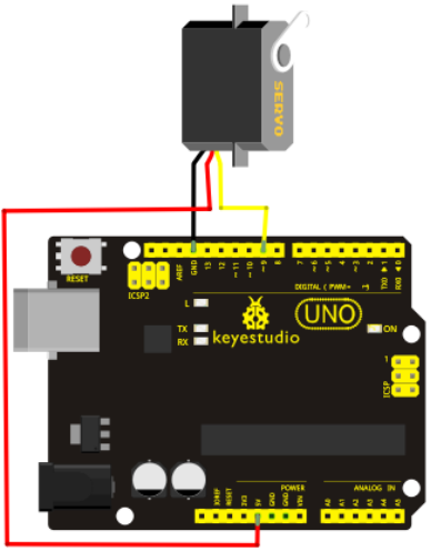
Connect the motor to digital pin 9. Compile a program to control the motor to rotate in the commanded angle, and display the angle on the screen.
Motoru dijital pin 9'a bağlayın. Komut verilen açıda döndürülecek motoru kontrol etmek için programı derleyip ve açıyı ekranda görüntüleyelim.
Sample Code A: / Örnek Kod A
int servopin=9;// select digital pin 9 for servomotor signal line
int myangle;// initialize angle variable
int pulsewidth;// initialize width variable
int val;
void servopulse(int servopin,int myangle)// define a servo pulse function
{
pulsewidth=(myangle*11)+500;// convert angle to 500-2480 pulse width
digitalWrite(servopin,HIGH);// set the level of servo pin as "high”
delayMicroseconds(pulsewidth);// delay microsecond of pulse width
digitalWrite(servopin,LOW);// set the level of servo pin as "low”
delay(20-pulsewidth/1000);
}

void setup()
{
pinMode(servopin,OUTPUT);// set servo pin as "output”
Serial.begin(9600);// connect to serial port, set baud rate at "9600”
Serial.println("servo=o_seral_simple ready" ) ;
}
void loop()// convert number 0 to 9 to corresponding 0-180 degree angle, LED blinks corresponding number of time
{
val=Serial.read();// read serial port value
if(val>='0'&&val<='9')
{
val=val-'0';// convert characteristic quantity to numerical variable
val=val*(180/9);// convert number to angle
Serial.print("moving servo to ");
Serial.print(val,DEC);
Serial.println();
for(int i=0;i<=50;i++) // giving the servo time to rotate to commanded position
{
servopulse(servopin,val);// use the pulse function
}
}
}
Method 2: / Yöntem 2
Let's first take a look at the Arduino built-in servo function and some common statements.
1. attach(interface)——select pin for servo, can only use pin 9 or 10.
2. write(angle)——used to control the rotate angle of the servo, can set the angle among 0 degree to 180 degree.
3. read()——used to read the angle of the servo, consider it a function to read the value in the write() function.
4. attached()——determine whether the parameter of the servo is sent to the servo pin.
5. detach()—— disconnect the servo and the pin, and the pin(digital pin 9 or 10) can be used for PWM port.
Önce Arduino'nun yerleşik servo işlevine ve bazı genel ifadelere bir göz atalım.
1. attach (arayüz) —— servo için pin seçin, yalnızca 9 veya 10 pinlerini kullanabilirsiniz.
2. write (açı) —— servonun dönüş açısını yazmak, kontrol etmek için kullanılır, açıyı 0 derece ila 180 derece arasında ayarlayabilirsiniz.
3. read () —— servonun açısını okumak için kullanılır. Bunu, write () işlevindeki değeri okumak için bir işlev olarak düşünün.
4. attached () —— servo parametresinin servo pinine gönderilip gönderilmediğini denetler.
5. detach () —— servoyu ve pini çıkarın, ve pim (dijital pim 9 veya 10) PWM portu için kullanılabilir.
Note: the written form of the above statements are " servo variable name. specific statement ()", e.g. myservo. Attach (9).
Still, connect the servo to pin 9.
Not: Yukarıdaki ifadelerde yazılabilir değişkenler sadece "servo değişkeni adı" ve "Özel değer ()"dir. örneğin: benimservom. attach (9).
Yani, servoyu pim 9'a bağla.
Sample Code B: / Örnek Kod B
#include/* define a header file. Special attention here, you can call the servo function directly from Arduino's software menu bar Sketch>Importlibrary>Servo, or input #include . Make sure there is a space between #include and . Otherwise, it will cause compile error.*/ Servo myservo;// define servo variable name void setup() { myservo.attach(9);// select servo pin(9 or 10) } void loop() { myservo.write(90);// set rotate angle of the motor }
Above are the two methods to control the servo. You can choose either one according to your liking or actual need.
Yukarıda servoyu kontrol etmenin iki yöntemi verilmiştir. İsteğinize veya ihtiyacınıza göre birini seçebilirsiniz.
5. Kaynaklar
Video
http://www.keyestudio.com/wp/ks0069-72-73/
https://drive.google.com/drive/folders/1rq0BzIjfrSJL9DOdKW8xjqtbqMkk5TlP?usp=sharing