


Keyestudio UNO R3 Breadboard Seti
Contents (Hızlı Menü)
- 1 UNO R3 Breadboard kit for Arduino / Arduino için UNO R3 Breadboard Kit
- 2 Introduction / Tanıtım
- 3 Kit Contents / Kit İçeriği
- 4 Introduction of keyestudio UNO R3 / Keyestudio UNO R3 Tanıtımı
- 5 Getting Started / Başlangıç
- 6 Project Details / Proje Detayları
- 6.1 Project 1: Hello World / Merhaba Dünya
- 6.2 Project 2: LED Blinking / Yanıp Sönen LED
- 6.3 Project 3:Traffic Light / Trafik Işığı
- 6.4 Project 4: LED Chasing Effect / Led Takip Efekti
- 6.5 Project 5: Button-controlled LED / Buton Kontrollü LED
- 6.6 Project 6: Responder experiment / Tepki Deneyi
- 6.7 Project 7: Active Buzzer / Aktif Buzzer
- 6.8 Project 8: Passive Buzzer / Pasif Buzzer
- 6.9 Project 9: RGB LED / RGB LED
- 6.10 Project 10: Analog Value Reading / Analog Değer Okuma
- 6.11 Project 11: Photo Resistor / Fotorezistör
- 6.12 Project 12: Flame Sensor / Alev Sensörü
- 6.13 Project 13: Analog temperature (thermistor) / Analog Sıcaklık (Termistör)
- 6.14 Project 14: LM35 Temperature Sensor / LM35 Sıcaklık Sensörü
- 6.15 Project 15: A cup with temperature indicator / Sıcaklık Göstergeli Kap
- 6.16 Project 16: DHT11 Temperature and Humidity Sensor / DHT11 Sıcaklık ve Nem Sensörü
- 6.17 Project 17: Tilt Switch / Eğim Kontağı
- 6.18 Project 18: Magical Light Cup / Sihirli Işık Kabı
- 6.19 Project 19: 1-digit LED Segment Display / 1-basamak LED Segment Ekran
- 6.1 Project 1: Hello World / Merhaba Dünya
- 7 Resources / Kaynaklar
UNO R3 Breadboard kit for Arduino / Arduino için UNO R3 Breadboard Kit
1. Introduction / Tanıtım
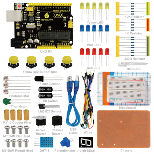
UNO R3 Breadboard kit is a learning kit based on UNO R3 development board. It's equipped with basic elements for ARDUINO experiments, including breadboard, Dupont wires, LEDs, resistors. With this kit, you can perform simple LED experiments, such as LED blinking, LED chasing effect, etc. It is both affordable and portable for your Arduino learning.
UNO R3 Breadboard kiti, UNO R3 geliştirme kartına dayalı bir öğrenme kitidir. Breadboard, Dupont telleri, LED'ler, dirençler de dahil olmak üzere ARDUINO deneyleri için temel unsurlarla donatılmıştır. Bu kitle, LED yanıp sönme, LED takip efekti vb. gibi basit LED deneyleri yapabilirsiniz. Arduino öğreniminiz için hem uygun maliyetli hem de taşınabilir.
2. Kit Contents / Kit İçeriği
- 1*keyestudio UNO R3 Denetleyici
- 30*Kablo
- 4*M3*10 Bakır Sütun
- 4*M3*6MM Düz Baş Vida
- 4*M3*6MM Yuvarlak Baş Vida
- 4*Sarı Kapak Buton
- 1*Breadboard
- 1*Şase
- 1*1-basamak SDsp
- 1*Aktif Buzzer
- 1*Pasif Buzzer
- 1*Termistör
- 5*10K Ohm Direnç
- 5*1K Ohm Direnç
- 8*220 Ohm Direnç
- 2*Eğim Kontağı
- 3*Fotorezistör
- 1*Alev Sensör
- 1*DHT11 Sensör
- 1*LM35DZ Sensör
- 4*Dokunmatik Kontak
- 1*RGB LED
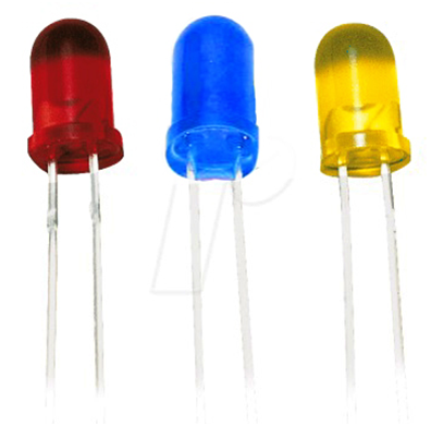
- 5*Mavi LED
- 5*Sarı LED
- 5*Kırmızı LED
- 1*Potansiyometre
- 1*Usb Kablo
3. Introduction of keyestudio UNO R3 / Keyestudio UNO R3 Tanıtımı
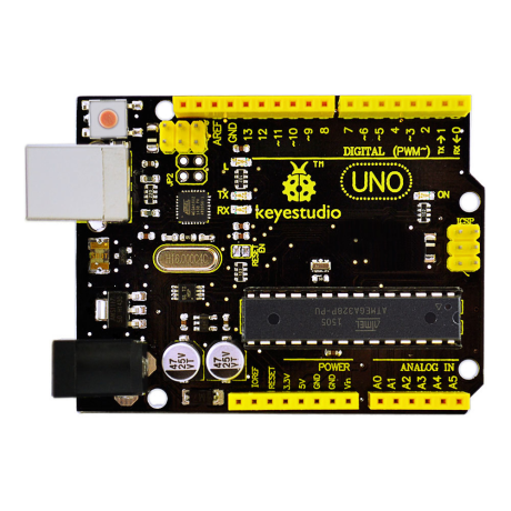
- Microcontroller: ATmega328
- Operating Voltage: 5V
- Input Voltage (recommended) : 7-12V
- Input Voltage (limits): 6-20V
- Digital I/O Pins: 14 (of which 6 provide PWM output)
- Analog Input Pins: 6
- DC Current per I/O Pin: 20 mA
- DC Current for 3.3V Pin: 50 mA
- Flash Memory: 32 KB (ATmega328) of which 0.5 KB used by bootloader
- SRAM: 2 KB (ATmega328)
- EEPROM: 1 KB (ATmega328)
- Clock Speed: 16 MHz
- Kit dimensions: 160*92*42
- Mikrodenetleyici: ATmega328
- Çalışma Gerilimi: 5V
- Giriş Voltajı (önerilir): 7-12V
- Giriş Voltajı (limitler): 6-20V
- Dijital I / O Pinleri: 14 (6 tanesi PWM çıkışı sağlar)
- Analog Giriş Pinleri: 6
- I / O Pin Başına DC Akım: 20 mA
- 3.3V Pin için DC Akım: 50 mA
- Flash Bellek: 32 KB (ATmega328), bunun 0,5 KB'si bootloader tarafından kullanılıyor
- SRAM: 2 KB (ATmega328)
- EEPROM: 1 KB (ATmega328)
- Saat Hızı: 16 MHz
- Kit ebat: 160*92*42
See http://arduino.cc for detailed specifications, overviews, schematics, etc. Core functions, code examples, and links to many of the device libraries can be found in the learning section; refer to the manufacturer's site if using other add-on shields or sensors.
The latest Arduino Integrated Development Environment (IDE) necessary for programming your UNO R3 board can be obtained at http://arduino.cc/en/Main/Software (the Download menu choice on Arduino.cc)
Examples for many basic components can be found under the Examples menu. As you install libraries for additional shields, new examples may be available.
Follow the getting started guide found on the arduino.cc web site. Click Learning, and select Getting started. Click on the link for Windows, Mac OS X, or Linux for more specific directions.
Ayrıntılı özellikler, genel özellikler, şemalar, vb. İçin http://arduino.cc adresine bakabilirsiniz. Temel işlevler, kod örnekleri ve cihaz kütüphanelerinin linkleri öğrenme bölümünde bulunabilir; başka eklenti shieldi veya sensörler kullanıyorsanız üreticinin sitesine bakın.
UNO R3 kartını programlamak için gerekli olan en son yazılım, Arduino Entegre Geliştirme Ortamı (IDE), http://arduino.cc/en/Main/Software adresinde bulunabilir (Download menüsünde).
Örnekler menüsünde birçok temel bileşen için örnekler bulunabilir. Ek shieldler için ek kitaplıklar kurduğunuzda, yeni örnekler de yapılabilir.
Arduino.cc web sitesinde bulunan başlangıç kılavuzunu takip edin. 'Learning'e tıklayın ve 'Getting Started'ı seçin. İşletim sisteminize uygun talimatlar için Windows, Mac OS X veya Linux linkini tıklayın.
4. Getting Started / Başlangıç
1. Download the Arduino Environment (IDE) and install or unzip/extract the application directory.
2. Connect the UNO board to one of your computer's USB port.
3. Install the drivers (If the computer does not automatically download and install the necessary USB drivers, point the hardware setup to the "drivers" directory of the Arduino IDE application.)
4. Launch the Arduino IDE application
5. Open a sketch example such as "Blink"
6. Select your Board from the Tools menu.
7. Select the Serial Port used by the board
8. Upload the sketch to the board
1. Arduino yazılımını (IDE) indirin ve uygulama zip dizinini açıp kurun.
2. UNO kartını bilgisayarınızın USB portundan birine bağlayın.
3. Sürücüleri kurun (Bilgisayarınız gerekli USB sürücülerini otomatik olarak indirip kurmazsa, donanım kurulumunu Arduino IDE uygulamasının "sürücüler" dizinine yönlendirin.)
4. Arduino IDE uygulamasını başlatın
5. "Blink" (Led yakma) gibi bir taslak örneği açın
6. Anakartınızı Araçlar menüsünden seçin.
7. Kart tarafından kullanılan Seri Bağlantı (COM) Noktasını seçin
8. Taslağı Karta yükleyin
5. Project Details / Proje Detayları
Project 1: Hello World / Merhaba Dünya
Introduction: / Tanıtım
As for starters, we will begin with something simple. In this project, you only need an Arduino and a USB cable to start the "Hello World!" experiment.This is not only a communication test of your Arduino and PC, but also a primer project for you to have your first try in the Arduino world!
Yeni başlayanlar için basit bir şeyle başlayacağız. Bu "Hello World!" (Merhaba Dünya) projesini başlatmak için sadece bir Arduino kart ve bir USB kablosuna ihtiyacınız var. deneme. Bu sadece Arduino ve PC'nizin (kişisel bilgisayarınızın) bir iletişim testi değil, aynı zamanda Arduino dünyasındaki ilk denemeniz için bir başlangıç projesidir!
Hardware Required: / Gerekli Donanım
1. Arduino board x1
2. USB cable x1
1. Arduino kart x1
2. USB kablosu x1
Sample Code: / Örnek Kod
After installing driver for Arduino, let's open Arduino software and compile the code that enables Arduino to print"Hello World!" under your instruction. Of course, you can compile the code for Arduino to continuously echo "Hello World!" without instruction. A simple If () statement will do the instruction trick. With the onboard LED connected to pin 13, you can instruct the LED to blink first when Arduino gets an instruction and then print the character"Hello World!”.
Arduino için sürücüyü kurduktan sonra, Arduino yazılımını açalım ve Arduino'nun "Hello World!" yazması için kodları girelim. Basit bir If () talimatı ile Arduino'nun sürekli ve aralıklı "Hello World!" yazmasını da sağlayabilirsiniz. Arduino bir talimat aldığında, Pin 13'e bağlı yerleşik LED'in, önce yanıp sönmesini, ardından "Merhaba Dünya!" yazdırmasını da sağlayabilirsiniz.
int val;//define variable val
int ledpin=13;// define digital interface 13
void setup()
{
Serial.begin(9600);// set the baud rate at 9600 to match the software set up. When connected to a specific device, (e.g. bluetooth), the baud rate needs to be the same with it.
pinMode(ledpin,OUTPUT);// initialize digital pin 13 as output. When using I/O ports on an Arduino, this kind of set up is always needed.
}
void loop()
{
val=Serial.read();// read the instruction or character from PC to Arduino, and assign them to Val.
if(val=='R')// determine if the instruction or character received is "R”.
{  // if it’s "R”,
digitalWrite(ledpin,HIGH);// set the LED on digital pin 13 on.
delay(500);
digitalWrite(ledpin,LOW);// set the LED on digital pin 13 off.
delay(500);
Serial.println("Hello World!");// display"Hello World!”string.
}
}
Result: / Sonuç
Click serial port monitor
Input R
LED 13 will blink once
PC will receive information from Arduino: Hello World
Seri port monitörüne tıklayın
kutucuğa R yazın
LED 13 bir kez yanıp sönecektir
PC Arduino'dan bilgi alacaktır: Merhaba Dünya
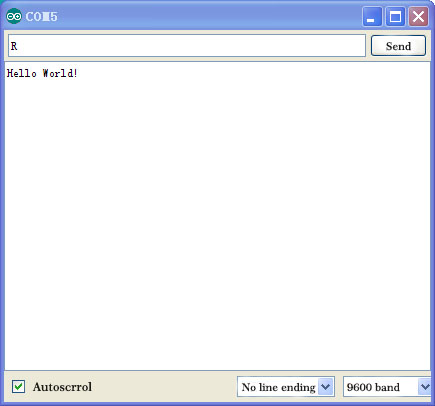
After choosing the right port, the experiment is very easy for you!
Doğru portu seçtiktiyseniz, deney sizin için çok kolaydır!
Project 2: LED Blinking / LED Yakıp Söndürme
Introduction: / Tanıtım
Blinking LED experiment is quite simple. In the "Hello World!" program, we have come across LED. This time, we are going to connect an LED to one of the digital pins rather than using LED13 which is soldered to the board. Apart from an Arduino and a USB cable, you will need extra parts as below:
Yanıp sönen LED deneyi oldukça basittir. "Merhaba Dünya!" programda LED ile tanıştık. Bu kez, karta lehimlenmiş LED13'ü kullanmak yerine dijital pinlerden birine LED bağlayacağız. Bir Arduino kart ve bir USB kablosunun yanı sıra, aşağıdaki gibi ekstra parçalara ihtiyacınız olacaktır:
Hardware Required:
1. Red M5 LED*1
2. 220? resistor*1
3. Breadboard*1
4. Breadboard jumper wires* several
1. Kırmızı M5 LED * 1
2. 220 Ohm direnç * 1
3. Breadboard * 1
4. Breadboard jumper kablo * birkaç adet
We follow below diagram from the experimental schematic link. Here we use digital pin 10. Connect an LED to a 220 ohm resistor to avoid high current damaging the LED.
Aşağıdaki şemayı takip edeceğiz. Burada dijital pin 10'u kullanıyoruz. Yüksek akımın LED'e zarar vermesini önlemek için LED'e 220 ohm bir direnç bağlayın.
Connection for UNO R3: / UNO R3 Bağantısı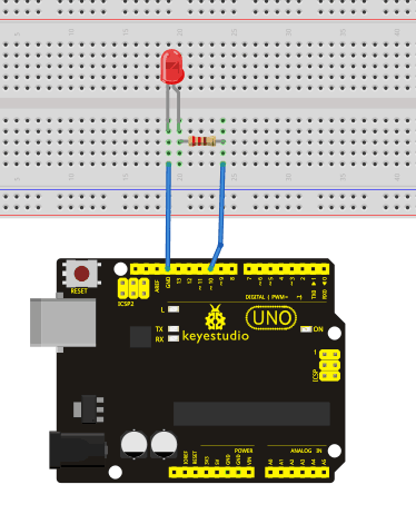
Sample Code: / Örnek Kod
int ledPin = 10; // define digital pin 10.
void setup()
{
pinMode(ledPin, OUTPUT);// define pin with LED connected as output.
}
void loop()
{
digitalWrite(ledPin, HIGH); // set the LED on.
delay(1000); // wait for a second.
digitalWrite(ledPin, LOW); // set the LED off.
delay(1000); // wait for a second
}
Result: / Sonuç
After downloading this program, in the experiment, you will see the LED connected to pin 10 turning on and off, with an interval approximately one second. The blinking LED experiment is now completed.
Kodu yükledikten sonra, deneyde, pin 10'a bağlı LED'in yaklaşık bir saniye aralıklarla yanıp söndüğünü göreceksiniz. Yanıp sönen LED deneyi şimdilik tamamlanmıştır.
Project 3:
Traffic Light / Trafik Işıkları
Introduction: / Tanıtım
In the previous program, we have done the LED blinking experiment with one LED. Now, it’s time to up the stakes and do a bit more complicated experiment-traffic light. Actually, these two experiments are similar. While in this traffic light experiment, we use 3 LEDs with different color rather than one LED.
Önceki programda, bir LED kullanarak yanıp sönen LED deneyi yaptık. Şimdi, zorlukları artırmanın ve biraz daha karmaşık deney olan trafik ışığı yapmanın zamanı geldi. Aslında, bu iki deney birbirine benziyor. Bu trafik ışığı deneyinde, bir LED yerine farklı renkte 3 LED kullanıyoruz.
Hardware Required: / Gerekli Donanım
1. Arduino board *1
2. USB cable *1
3. Red M5 LED*1
4. Yellow M5 LED*1
5. Green M5 LED*1
6. 220? resistor *3
7. Breadboard*1
8. Breadboard jumper wires* several
1. Arduino kart * 1
2. USB kablosu * 1
3. Kırmızı M5 LED * 1
4. Sarı M5 LED * 1
5. Yeşil M5 LED * 1
6. 220 Ohm direnç * 3
7. Breadboard * 1
8. Breadboard jumper kablosu * birkaç adet
Connection for UNO R3: / UNO R3 Bağlantısı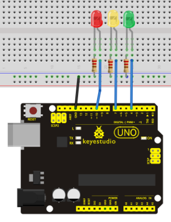
Sample Code: / Örnek Kod
Since it is a simulation of traffic light, the blinking time of each LED should be the same with those in traffic light system. In this program, we use Arduino delay () function to control delay time, which is much simpler than C language.
Trafik ışığının bir simülasyonu olduğundan, her bir LED'in yanıp sönme süresi trafik ışığı sistemindekiyle aynı olmalıdır. Bu programda, C dilinden daha basit olarak, gecikme süresini kontrol etmek için Arduino delay () fonksiyonunu kullanıyoruz.
int redled =10; // initialize digital pin 8.
int yellowled =7; // initialize digital pin 7.
int greenled =4; // initialize digital pin 4.
void setup()
{
pinMode(redled, OUTPUT);// set the pin with red LED as "output”
pinMode(yellowled, OUTPUT); // set the pin with yellow LED as "output”
pinMode(greenled, OUTPUT); // set the pin with green LED as "output”
}
void loop()
{
digitalWrite(greenled, HIGH);//// turn on green LED
delay(5000);// wait 5 seconds

digitalWrite(greenled, LOW); // turn off green LED
for(int i=0;i<3;i++)// blinks for 3 times
{
delay(500);// wait 0.5 second
digitalWrite(yellowled, HIGH);// turn on yellow LED
delay(500);// wait 0.5 second
digitalWrite(yellowled, LOW);// turn off yellow LED
}
delay(500);// wait 0.5 second
digitalWrite(redled, HIGH);// turn on red LED
delay(5000);// wait 5 second
digitalWrite(redled, LOW);// turn off red LED
}
Result: / Sonuç
When the uploading process is completed, you can see traffic lights of your own design.
Note: this circuit design is very similar with the one in LED chasing effect.
The green light will be on for 5 seconds, and then off, followed by the yellow light blinking for 3 times, and then the red light is on for 5 seconds, repeatedly forming a cycle.
Experiment is now completed.
Yükleme işlemi tamamlandığında, kendi tasarımınız olan trafik ışıklarını görebilirsiniz.
Not: Bu devre tasarımı LED takip efektindeki ile çok benzer.
Yeşil ışık 5 saniye boyunca yanacak ve ardından sönecek, ardından sarı ışık 3 kez yanıp sönecek ve ardından kırmızı ışık 5 saniye boyunca yanacak ve bu şekilde tekrarlayan bir döngü oluşacaktır.
Deney şimdi tamamlandı.
Project 4: LED Chasing Effect / LED Takip Efekti
Introduction: / Tanıtım
We often see billboards composed of colorful LEDs. They are constantly changing to form various effects. In this experiment, we compile a program to simulate chase effect.
Sık sık renkli LED'lerden oluşan reklam panoları görürüz. Çeşitli efektler oluşturmak için sürekli değişiyorlar. Bu deneyde,bu efektleri elde etmek için bir program derledik.
Hardware Required: / Gerekli Donanım
1. Led x6
2. 220? resistor x6
3. Colorful breadboard wires
1. Led x 6
2. 220 Ohm direnç x 6
3. Renkli breadboard kabloları
Connection for UNO R3: / UNO R3 Bağlantısı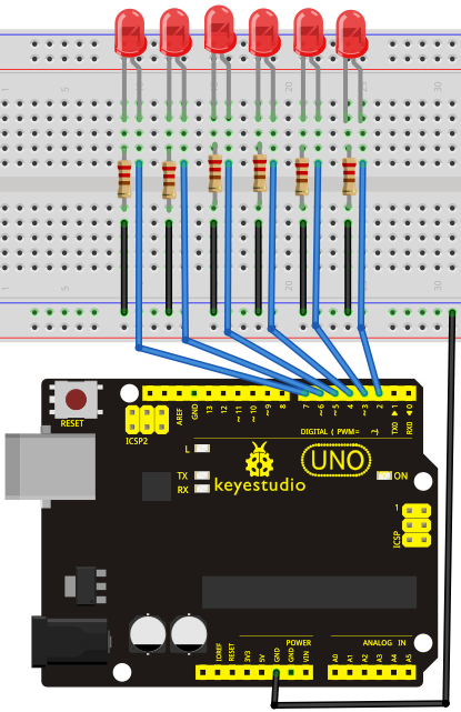
Sample Code: / Örnek Kod
int BASE = 2 ;  // the I/O pin for the first LED
int NUM = 6;   // number of LEDs

void setup()
{
   for (int i = BASE; i < BASE + NUM; i ++)
   {
     pinMode(i, OUTPUT);   // set I/O pins as output
   }
}

void loop()
{
   for (int i = BASE; i < BASE + NUM; i ++)
   {
     digitalWrite(i, LOW);    // set I/O pins as "low”, turn off LEDs one by one.
     delay(200);        // delay
   }
   for (int i = BASE; i < BASE + NUM; i ++)
   {
     digitalWrite(i, HIGH);    // set I/O pins as "high”, turn on LEDs one by one
     delay(200);        // delay
   }
}
Result: / Sonuç
You can see the LEDs blink by sequence.
LED'lerin sırayla yanıp söndüğünü görebilirsiniz.
Project 5: Button-controlled LED / Buton ile LED Kontrolü
Introduction: / Tanıtım
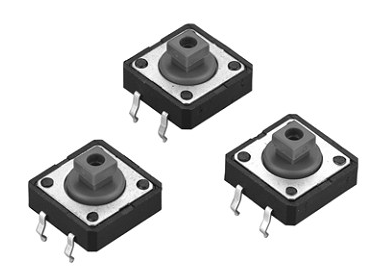
I/O port means interface for INPUT and OUTPUT. Up until now, we have only used its OUTPUT function. In this experiment, we will try to use the input function, which is to read the output value of device connecting to it. We use 1 button and 1 LED using both input and output to give you a better understanding of the I/O function. Button switches, familiar to most of us, are a switch value (digital value) component. When it's pressed,the circuit is in closed (conducting) state.
I / O (Input/Output) portu GİRİŞ ve ÇIKIŞ için arabirim anlamına gelir. Şimdiye kadar yalnızca OUTPUT işlevini kullandık. Bu deneyde, bağlı bir cihazın çıkış değerini okumak için kartın giriş işlevini kullanmaya çalışacağız. I / O işlevini daha iyi anlayabilmeniz için hem girişi hem de çıkışı kullanmak üzere 1 buton (düğme) ve 1 LED bağlayacağız. Çoğumuzun bildiği buton anahtarları, aslında bir anahtar değer (dijital değer) bileşenidir. Basıldığında, devre kapalı (iletken) durumdadır.
Hardware Required: / Gerekli Donanım
1. Button switch*1
2. Red M5 LED*1
3. 220? resistor*1
4. 10K? resistor*1
5. Breadboard*1
6. Breadboard jumper wires*several
1. Buton anahtarı * 1
2. Kırmızı M5 LED * 1
3. 220 Ohm direnç * 1
4. 10K Ohm direnç * 1
5. Breadboard * 1
6. Breadboard jumper kablo * birkaç adet
Connection for UNO R3: / UNO R3 Bağlantısı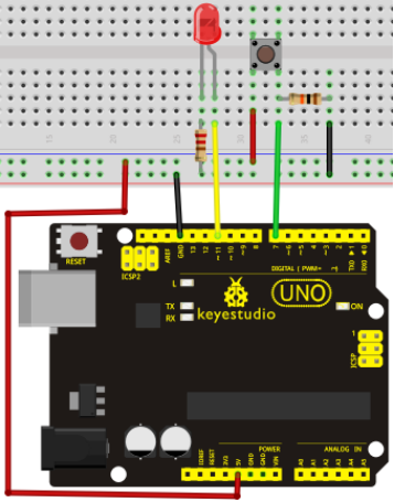
Sample Code: / Örnek Kod
Now, let's begin the compiling. When the button is pressed, the LED will be on. Based on the previous study, the coding may be easy for you. In this program, we add a statement of judgment. Here, we use an if () statement.
Arduino IDE is based on C language, so statements of C language such as while, switch etc. can certainly be used for Arduino program.
When we press the button, pin 7 will output high level. We can program pin 11 to output high level and turn on the LED. When pin 7 outputs low level, pin 11 also outputs low level and the LED remains off.
Şimdi Kod derlemeye başlayalım. Düğmeye basıldığında, LED yanacaktır. Önceki çalışmaya bakarak, bu kodlama sizin için kolay gelebilir. Bu programda, bir kural ekleyeceğiz. Burada bir if () ifadesi kullanacağız.
Arduino IDE, C diline dayanmaktadır, bu nedenle, while, switch vb. gibi C dili ifadeleri kesinlikle Arduino programı için kullanılabilir.
Düğmeye bastığımızda, pin 7 yüksek seviye sinyal çıkacaktır. Bu durumdayken Pin 11'i yüksek seviye sinyal çıkacak ve LED'i açacak şekilde programlayabiliriz. Pin 7 düşük seviye çıktığı zaman pin 11 de düşük seviye çıkışı verir ve LED kapalı kalır.
int ledpin=11;// pin 11'i aç
int inpin=7;// pin 7'yi aç
int val;// value(değer) tanımla
void setup()
{
pinMode(ledpin,OUTPUT);// LED pini "çıkış" olarak ata
pinMode(inpin,INPUT);// button pini "giriş” olarak ata

}
void loop()
{
val=digitalRead(inpin);// pin 7'nin seviye değerini oku ve if'i val değerine ata
if(val==LOW)// buton basılı mı diye kontrol et, basılıysa LED'i yak, yoksa söndür.
{ digitalWrite(ledpin,LOW);}
else
{ digitalWrite(ledpin,HIGH);}
}
Result: / Sonuç
When the button is pressed, LED is on, otherwise, LED remains off. So the button controlled LED experiment is completed. The simple principle of this experiment is widely used in a variety of circuit and electric appliances. You can easily come across it in your everyday life. One typical example is when you press a certain key of your phone, the backlight will be on.
Düğmeye basıldığında LED yanar, aksi halde LED kapalı kalır. Böylece buton kontrollü LED deneyi tamamlandı. Bu deneyin basit prensibi çeşitli devre ve elektrikli cihazlarda yaygın olarak kullanılmaktadır. Günlük yaşamınızda kolayca karşılaşabilirsiniz. Tipik bir örnek, telefonunuzun belirli bir tuşuna bastığınız zaman, arka ışık yanacaktır.
Project 6: Responder experiment / Tepki Deneyi
Introduction:
After completing all the previous experiments, we believe you will find this one easy. In this program, we have 3 buttons and a reset button controlling the corresponding 3 LEDs, using 7 digital I/O pins.
Önceki tüm deneyleri tamamladıktan sonra, bunu kolay bulacağınıza inanıyoruz. Bu programda, 7 dijital I / O pini kullanarak 3 düğmemiz ve ilgili 3 LED'i kontrol eden bir reset düğmemiz var.
Hardware required: / Gerekli Donanım
1. Uno R3 board *1
2. USB Cable *1
3. Button switch*4
4. Red M5 LED*1
5. Yellow M5 LED*1
6. Blue M5 LED*1
7. 220 Ohm resistor*3
8. 10 KOhm resistor*4
9.Breadboard*1
10.Breadboard jumper wires* several
1. Uno R3 kartı * 1
2. USB Kablosu * 1
3. Düğme anahtarı * 4
4. Kırmızı M5 LED * 1
5. Sarı M5 LED * 1
6. Mavi M5 LED * 1
7. 220 Ohm direnç * 3
8. 10 KOhm direnç * 4
9. Breadboard * 1
10. Breadboard jumper kablosu * birkaç adet
Circuit connection: / Bağlantı Şeması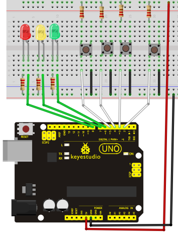
Sample Code: / Örnek Kod
int redled=8;     // set red LED as "output”
int yellowled=7;  // set yellow LED as "output”
int blueled=6;   // set blue LED as "output”
int redpin=5;     // initialize pin for red button
int yellowpin=4;  // initialize pin for yellow button
int bluepin=3;   // initialize pin for blue button
int restpin=2;   // initialize pin for reset button
int red;
int yellow;
int blue;
void setup()
{
pinMode(redled,OUTPUT);
pinMode(yellowled,OUTPUT);
pinMode(blueled,OUTPUT);
pinMode(redpin,INPUT);
pinMode(yellowpin,INPUT);
pinMode(bluepin,INPUT);
}
void loop()  // repeatedly read pins for buttons
{
red=digitalRead(redpin);
yellow=digitalRead(yellowpin);
blue=digitalRead(bluepin);
if(red==LOW)RED_YES();
if(yellow==LOW)YELLOW_YES();
if(blue==LOW)BLUE_YES();
}

void RED_YES()// execute the code until red light is on; end cycle when reset button is pressed
{
  while(digitalRead(restpin)==1)
  {
   digitalWrite(redled,HIGH);
   digitalWrite(blueled,LOW);
   digitalWrite(yellowled,LOW);
  }
  clear_led();
}
void YELLOW_YES()// execute the code until yellow light is on; end cycle when reset button is pressed
{
  while(digitalRead(restpin)==1)
  {
  digitalWrite(redled,LOW);
  digitalWrite(blueled,LOW);
  digitalWrite(yellowled,HIGH);
  }
  clear_led();
}
void BLUE_YES()// execute the code until green light is on; end cycle when reset button is pressed
{
  while(digitalRead(restpin)==1)
  {
  digitalWrite(redled,LOW);
  digitalWrite(blueled,HIGH);
  digitalWrite(yellowled,LOW);
  }
  clear_led();
}
void clear_led()// all LED off
{
  digitalWrite(redled,LOW);
  digitalWrite(blueled,LOW);
  digitalWrite(yellowled,LOW);
}
Result: / Sonuç
Whichever button is pressed first, the corresponding LED will be on!
Then press the RESET button to reset.
After the above process, we have built our own simple responder.
Hangi düğmeye basılırsa, ilgili LED yanacaktır!
Ardından sıfırlamak için RESET düğmesine basın.
Yukarıdaki işlemle, kendi tepki devremizi oluşturmuş olduk.
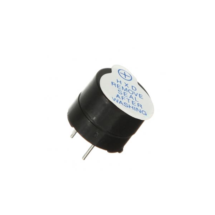
Project 7: Active Buzzer / Aktif Buzzer
Introduction:
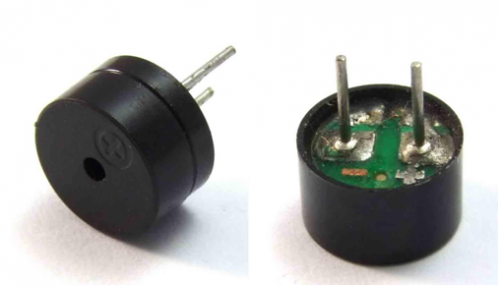
Active buzzer is widely used on computer, printer, alarm, electronic toy, telephone, timer etc as a sound making element. It has an inner vibration source. Simply connect it with 5V power supply, it can buzz continuously.
Aktif buzzer (Sesli uyarıcı); bilgisayar, yazıcı, alarm, elektronik oyuncak, telefon, zamanlayıcı, vb. cihazlarda sesli uyarıcı olarak yaygın şekilde kullanılır. İç titreşim kaynağına sahiptir. Basitçe 5V güç kaynağı bağlayın, sürekli vızıltı sesi (buzz) verebilir.
Hardware Required:
1. Uno R3 board *1
2.USB Cable *1
3.Active Buzzer*1
4.Breadboard*1
5.Breadboard jumper wires* several
1. Uno R3 kartı * 1
2. USB Kablosu * 1
3. Aktif Buzzer * 1
4. Breadboard * 1
5. Breadboard jumper kablo * birkaç adet
Connection for UNO R3: / UNO R3 Bağlantısı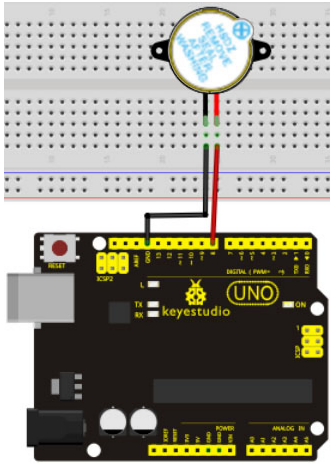
When connecting the circuit, pay attention to the positive & the negative poles of the buzzer. In the photo, you can see there are red and black lines. When the circuit is finished, you can begin programming.
Devreyi bağlarken, buzzerin pozitif ve negatif kutuplarına dikkat edin. Fotoğrafta kırmızı ve siyah çizgiler olduğunu görebilirsiniz. Devre tamamlandığında, programlamaya başlayabilirsiniz.
Sample Code:
Program is simple. You control the buzzer by outputting high/low level.
Program basittir. Buzzer'ı yüksek/düşük seviye sinyalle kontrol edebilirsiniz.
int buzzer=8;// initialize digital IO pin that controls the buzzer
void setup()
{
  pinMode(buzzer,OUTPUT);// set pin mode as "output”
}
void loop()
{
digitalWrite(buzzer, HIGH); // produce sound
}
Result: / Sonuç
After downloading the program, the buzzer experiment is completed. You can see the buzzer is ringing.
Programı yükledik ve buzzer deneyi tamamlandı. Buzzer'ın öttüğünü duyabilirsiniz
Project 8: Passive Buzzer / Pasif Buzzer
Introduction:
We can use Arduino to make many interactive works of which the most commonly used is acoustic-optic display. All the previous experiment has something to do with LED. However, the circuit in this experiment can produce sound. Normally, the experiment is done with a buzzer or a speaker while buzzer is simpler and easier to use. The buzzer we introduced here is a passive buzzer. It cannot be actuated by itself, but by external pulse frequencies. Different frequencies produce different sounds. We can use Arduino to code the melody of a song, which is actually quite fun and simple.
Arduino'yu birçok interaktif çalışma yapmak için kullanabilirsiniz. En sık kullanılan örnek akustik-optik ekrandır. Önceki deneyler LED ile ilgiliydi. Fakat, bu deney devresi ses üretebilir. Normalde bu deney basit ve kolay olması açısından bir buzzer ile yapılır, veya bir hoparlör ile de yapılabilir. Burada tanıttığımız pasif bir buzzer'dır. Kendiliğinden değil, harici sinyal frekansları tarafından çalıştırılabilir. Farklı frekanslar farklı sesler üretir. Arduino'yu, çok eğlenceli ve basit bir şarkının melodisini kodlamak için kullanabilirsiniz.
Hardware Required: / Gerekli Donanım
1. Uno R3 board *1
2. USB Cable *1
3. Passive buzzer*1
4. Breadboard*1
5. Breadboard jumper wires* several
1. Uno R3 kartı * 1
2. USB Kablosu * 1
3. Pasif zil * 1
4. Breadboard * 1
5. Breadboard jumper kablo * birkaç adet
Circuit connection: / Bağlantı Şeması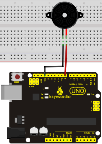
Sample Code: / Örnek Kod
int buzzer=8;// select digital IO pin for the buzzer
void setup()
{
pinMode(buzzer,OUTPUT);// set digital IO pin pattern, OUTPUT to be output
}
void loop()
{ unsigned char i,j;//define variable
while(1)
{ for(i=0;i<80;i++)// output a frequency sound
{ digitalWrite(buzzer,HIGH);// sound
delay(1);//delay1ms
digitalWrite(buzzer,LOW);//not sound
delay(1);//ms delay
}
for(i=0;i<100;i++)// output a frequency sound
{ digitalWrite(buzzer,HIGH);// sound
digitalWrite(buzzer,LOW);//not sound
delay(2);//2ms delay
}
}
}
Result: / Sonuç
After downloading the program, the buzzer experiment is completed.
Programı yükledik ve sonra buzzer deneyi tamamlandı.
Project 9: RGB LED / RGB LED
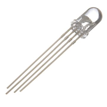
Introduction:
Tricolor principle to display various colors
PWM controlling ports to display full color
Can be driven directly by Arduino PWM interfaces
Çeşitli renkleri görüntülemek için üç-renk prensibi;
Tam renkli görüntülemek için PWM kontrol portları;
Doğrudan Arduino PWM arayüzleri tarafından yönetilebilir. 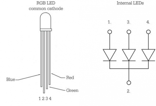
Hardware Required: / Gerekli Donanım
1. Uno R3 board *1
2.USB Cable *1
3.RGB LED *1
4.Breadboard*1
5.Breadboard jumper wires* several
1. Uno R3 kartı * 1
2. USB Kablosu * 1
3. RGB LED * 1
4. Breadboard * 1
5. Breadboard jumper kablo * birkaç adet
Connection for UNO R3: / UNO R3 Bağlantısı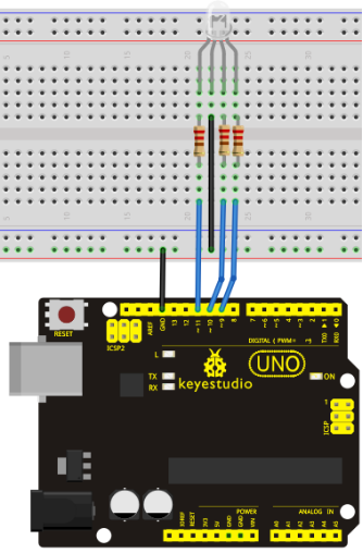
Sample Code:
int redpin = 11; //select the pin for the red LED
int bluepin =10; // select the pin for the blue LED
int greenpin =9;// select the pin for the green LED

int val;

void setup() {
  pinMode(redpin, OUTPUT);
  pinMode(bluepin, OUTPUT);
  pinMode(greenpin, OUTPUT);
  Serial.begin(9600);
}

void loop()
{
for(val=255; val>0; val--)
  {
   analogWrite(11, val);
   analogWrite(10, 255-val);
   analogWrite(9, 128-val);
   delay(1);
  }
for(val=0; val<255; val++)
  {
   analogWrite(11, val);
   analogWrite(10, 255-val);
   analogWrite(9, 128-val);
   delay(1);
  }
 Serial.println(val, DEC);
}
Result: / Sonuç
Directly copy the above code into arduino IDE, and click upload ![]() , wait a few seconds, you can see a full-color LED
, wait a few seconds, you can see a full-color LED
Yukarıdaki kodu doğrudan arduino IDE'ye kopyalayın ve yükleme dümesine ![]() tıklayın, birkaç saniye bekleyin, tam-renkli bir LED göreceksiniz.
tıklayın, birkaç saniye bekleyin, tam-renkli bir LED göreceksiniz.
Project 10: Analog Value Reading / Analog Değer Okuma
Introduction:
In this experiment, we will begin the learning of analog I/O interfaces. On an Arduino, there are 6 analog interfaces numbered from 0 to 5. These 6 interfaces can also be used as digital ones numbered as 14-19. After a brief introduction, let's begin our project. Potentiometer used here is a typical output component of analog value that is familiar to us.
Bu deneyde, analog I / O arayüzleri öğrenmeye başlayacağız. Bir Arduino'da, 0'dan 5'e kadar numaralandırılmış 6 analog arabirim vardır. Bu 6 arabirim, 14-19 olarak numaralandırabileceğimiz dijital arayüzler olarak da kullanılabilir. Bu kısa girişten sonra, hadi projemize başlayalım. Burada kullanılan potansiyometre, bize tanıdık olan tipik bir analog değer çıkış bileşenidir.
Hardware Required: / Gerekli Donanım
1. Uno R3 board *1
2. USB Cable *1
3. Potentiometer *1
4. Breadboard*1
5. Breadboard jumper wires* several
1. Uno R3 kartı * 1
2. USB Kablosu * 1
3. Potansiyometre * 1
4. Breadboard * 1
5. Breadboard jumper kablo * birkaç adet
Connection:
In this experiment, we will convert the resistance value of the potentiometer to analog ones and display it on the screen. This is an application we need to master well for our future experiments.
Connection circuit as below:
Bu deneyde, potansiyometrenin direnç değerini analog değere dönüştürüp ekranda görüntüleyeceğiz. Bu, gelecekteki deneylerimiz için iyi bir şekilde ustalaşmanız gereken bir uygulamadır.
Bağlantı devresi aşağıdaki gibidir:
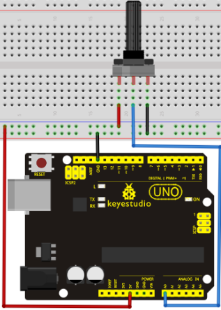
The analog interface we use here is interface 0.
Burada kullandığımız analog arayüz A0'dır.
Sample Code: / Örnek Kod
The program compiling is simple. An analogRead () Statement can read the value of the interface. The A/D acquisition of Arduino 328 is in 10 bits, so the value it reads is among 0 to 1023. One difficulty in this project is to display the value on the screen, which is actually easy to learn. First, we need to set the baud rate in voidsetup (). Displaying the value is a communication between Arduino and PC, so the baud rate of the Arduino should match the the one in the PC's software set up. Otherwise, the display will be messy codes or no display at all. In the lower right corner of the Arduino software monitor window, there is a button for baud rate set up. The set up here needs to match the one in the program. The statement in the program is Serial.begin(); enclosed is the baud rate value, followed by statement for displaying. You can either use Serial.print() or Serial.println() statement.
Programın derlenmesi basittir. Bir analogRead () ifadesi ile arayüzün değeri okunabilir. Arduino 328'in A/D (Analog/Dijital) edinimi 10 bittir, bu yüzden okuduğu değer 0 ile 1023 arasındadır. Bu projedeki zorluklardan biri, ekranda öğrenmesi çok kolay olan değeri göstermektir. Öncelikle voidsetup()'ta baud hızını ayarlamamız gerekiyor. Değerin görüntülenmesi, Arduino ve PC arasındaki bir iletişimdir, bu nedenle Arduino'nun baud hızı, PC'nin yazılımındaki ile aynı olmalıdır. Aksi takdirde, ekranda karman çorman kodlar olacak ya da hiç görüntülenmeyecektir. Arduino yazılımı monitör penceresinin sağ alt köşesinde, baud hızı ayarlaması için bir düğme vardır. Buradaki ayarın programdaki ile eşleşmesi gerekir. Programda "Serial.begin ();" ifadesindeki parantezin içeriği baud rate değeri olup, sonrasında görüntüleme ifadesiyle kullanılır; Serial.print () veya Serial.println () ifadesini kullanabilirsiniz.
int potpin=0;// initialize analog pin 0
int ledpin=13;// initialize digital pin 13
int val=0;// define val, assign initial value 0
void setup()
{
pinMode(ledpin,OUTPUT);// set digital pin as "output”
Serial.begin(9600);// set baud rate at 9600

}
void loop()
{
digitalWrite(ledpin,HIGH);// turn on the LED on pin 13
delay(50);// wait for 0.05 second
digitalWrite(ledpin,LOW);// turn off the LED on pin 13
delay(50);// wait for 0.05 second
val=analogRead(potpin);// read the analog value of analog pin 0, and assign it to val
Serial.println(val);// display val’s value
}
Result:
The sample program uses the built-in LED connected to pin 13. Each time the device reads a value, the LED blinks.
Below is the analog value it reads.
Örnek program kodu, pin 13'e bağlı dahili LED'i kullanır. Cihaz bir değer okuduğunda, LED yanıp söner.
Aşağıdaki görsel, okunan analog değerdir.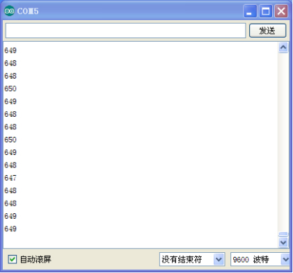
When you rotate the potentiometer knob, you can see the displayed value changes. The reading of analog value is a very common function since most sensors output analog value. After calculation, we can have the corresponding value we need. The experiment is now completed, thank you.
Potansiyometre düğmesini çevirdiğinizde, görüntülenen değer değişimini görebilirsiniz. Analog değerin okunması, çoğu sensör çıkışı analog değer olduğu için çok yaygın bir işlevdir. Hesaplamadan sonra ihtiyacınız olan değeri alabilirsiniz.
Deney şimdilik tamamlandı.
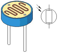
Project 11: Photo Resistor / Fotorezistör
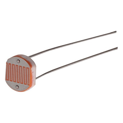
Introduction:
After completing all the previous experiments, we acquired some basic understanding and knowledge about Arduino application. We have learned digital input and output, analog input and PWM. Now, we can begin the learning of sensors applications.
Photo resistor (Photovaristor) is a resistor whose resistance varies according to different incident light strength. It's made based on the photoelectric effect of semiconductor. If the incident light is intense, its resistance reduces; if the incident light is weak, the resistance increases. Photovaristor is commonly applied in the measurement of light, light control and photovoltaic conversion (convert the change of light into the change of electricity).
Photo resistor is also being widely applied to various light control circuit, such as light control and adjustment, optical switches etc. We will start with a relatively simple experiment regarding to photovaristor application. Photovaristor is an element that will change its resistance as light strength changes. So need to read the analog values. When there is change in light strength, it will cause corresponding change on the LED.
Önceki tüm deneyleri tamamladıktan sonra, Arduino uygulaması hakkında temel bir anlayış ve bilgi edinmiş olmalısınız. Dijital giriş ve çıkış, analog giriş ve PWM'yi tanıttık. Şimdi, sensör uygulamalarını öğrenmeye başlayalım.
Fotorezistör (Fotovaristör), direnci farklı ışık güçlerinde farklı direnci olan bir dirençtir. Yarı iletken fotoelektrik etkisi esas alınarak yapılmıştır. Işık yoğunsa, direnci azalır; ışık zayıfsa direnç artar. Fotorezistör, genellikle ışık, ışık kontrolü ve fotovoltaik dönüşüm (ışığın değişimini elektrik değişikliğine dönüştürür) ölçümlerinde uygulanır .
Fotorezistör, ayrıca ışık kontrolü ve ayarı, optik anahtarlar vb. gibi çeşitli ışık kontrol devrelerinde yaygın olarak uygulanır. Fotorezistör uygulamasına oldukça basit bir deneyle başlayacağız. Fotorezistör, ışık gücü değiştikçe direncini değiştiren bir elementtir. Bu durumda analog değerleri okumalıyız. Işık gücünde bir değişiklik olduğunda, LED üzerinde ilgili bir değişikliğe neden olacaktır.
We will start with a relatively simple experiment regarding photovaristor application. Photovaristor is an element that changes its resistance as light strenth changes. So we will need to read the analog values. We can refer to the PWM experiment, replacing the potentiometer with photovaristor. When there is change in light strength, there will be corresponding change on the LED.
Hardware Required:
1. Uno R3 board *1
2. USB Cable *1
3. Photo resistor*1
4. Red M5 LED*1
5. 10 Kohm resistor*1
6. 220 ohm resistor*1
7. Breadboard*1
8. Breadboard jumper wires* several
1. Uno R3 kartı * 1
2. USB Kablosu * 1
3. Fotorezistör * 1
4. Kırmızı M5 LED * 1
5. 10 Kohm direnci * 1
6. 220 ohm direnç * 1
7. Breadboard * 1
8. Breadboard jumper kablo * birkaç adet
Circuit connection: /Bağlantı Şeması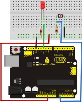
Sample Code:
After the connection, let's begin the program compiling.
Bağlantıdan sonra program derlemeye başlayalım.
int potpin=0;// initialize analog pin 0, connected with photovaristor
int ledpin=11;// initialize digital pin 11, output regulating the brightness of LED
int val=0;// initialize variable va
void setup()
{
pinMode(ledpin,OUTPUT);// set digital pin 11 as "output”
Serial.begin(9600);// set baud rate at "9600”
}
void loop()
{
val=analogRead(potpin);// read the analog value of the sensor and assign it to val
Serial.println(val);// display the value of val
analogWrite(ledpin,val);// turn on the LED and set up brightness(maximum output value 255)
delay(10);// wait for 0.01
}
Result:
After downloading the program, you can change the light strength around the photovaristor and see corresponding brightness change of the LED. Photovaristors has various applications in our everyday life. You can make other interesting interactive projects base on this one.
Programı indirdikten sonra, fotorezistöre yansıyan ışık gücünü değiştirebilir ve LED'de meydana getirdiği parlaklık değişimini görebilirsiniz. Fotorezistörlerin günlük yaşamımızda çeşitli uygulama alanları vardır. Buna dayanarak başka ilginç projeler de yapabilirsiniz.
Project 12: Flame Sensor / Alev Sensörü
Introduction: / Tanıtım
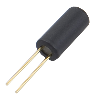
Flame sensor (Infrared receiving triode) is specially used on robots to find the fire source. This sensor is of high sensitivity to flame. Below is a photo of it.
Alev sensörü (Kızılötesi alıcı triyot) yangın kaynağını bulmak için özellikle robotlarda kullanılır. Bu sensör aleve karşı yüksek hassasiyete sahiptir. Aşağıda bir fotoğrafı var.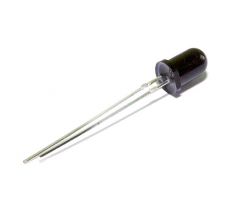
Working Principle: / Çalışma Prensibi
Flame sensor is based on the principle that infrared ray is highly sensitive to flame. It has an infrared receiving tube specially designed to detect fire, and then convert the flame brightness into fluctuating level signal. The signals are then input into the central processor and be dealt with accordingly.
Alev sensörü, alevlerden kızılötesi ışınınların yayılması ilkesine dayanır. Özel olarak alev algılamak için tasarlanmış bir kızılötesi alıcı tüpe sahiptir ve daha sonra alev parlaklığını dalgalı seviye sinyaline dönüştürür. Sinyaller daha sonra merkezi işlemciye girilir ve buna göre ele alınır.
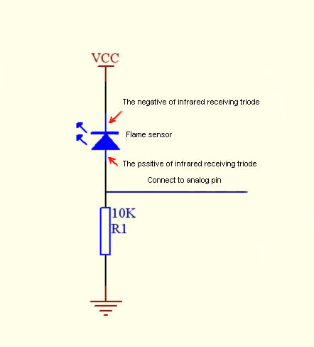
Sensor Connection: / Sensör Bağlantısı
The shorter lead of the receiving triode is for negative, the other one for positive. Connect negative to 5V pin, positive to resistor; connect the other end of the resistor to GND, connect one end of a jumper wire to a clip which is electrically connected to sensor positive, the other end to analog pin. As shown below:
Alıcı triyot sensörün daha kısa ayağı negatif, diğeri pozitiftir. Direncin bir ucunu sensörün pozitifine, diğer ucunu GND'ye (toprağa) bağlayın. Sensörün negatif ayağını 5V pine bağlayın; direncin , bir jumper kablo ile sensörün pozitif uzantısından bir hat alıp analog pine girin. Aşağıda gösterildiği gibi:
Hardware Required: / Gerekli Donanım
1. Uno R3 board *1
2. USB Cable *1
3. Flame sensor *1
4. Buzzer *1
5. 10 Kohm resistor *1
6. Breadboard*1
7. Breadboard jumper wires* several
1. Uno R3 kartı * 1
2. USB Kablosu * 1
3. Alev sensörü * 1
4. Zil * 1
5. 10 Kohm direnci * 1
6. Breadboard * 1
7. Breadboard jumper kablo * birkaç adet
Circuit connection: / Bağlantı Şeması
1)Connecting buzzer:
Connect the controller board, prototype board, breadboard and USB cable according to the Arduino tutorial. Connect the buzzer to digital pin 8.
2)Connecting flame sensor:
Connect the sensor to analog pin 0.
1) Buzzer'ın bağlanması:
Denetleyici kartı, prototip kartı, breadboardu ve USB kablosunu aşağıdaki görsele göre bağlayın. Buzzer'ı dijital pin 8'e bağlayın.
2) Alev sensörünün bağlanması:
Sensörü analog pin 0'a bağlayın.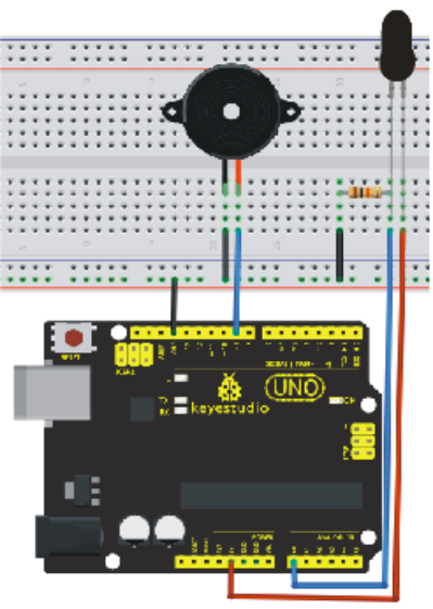
Experiment principle: / Deney Prensibi
When it's approaching a fire, the voltage value the analog port reads differs. If you use a multimeter, you can know when there is no fire approaching, the voltage it reads is around 0.3V; when there is fire approaching, the voltage it reads is around 1.0V, tthe nearer the fire, the higher the voltage. So in the beginning of the program, you can initialize voltage value i (no fire value); Then, continuously read the analog voltage value j and obtain difference value k=j-i; compare k with 0.6V (123 in binary) to determine whether or not there is a fire approaching; if yes, the buzzer will buzz.
Ateşe yaklaşırken, analog portun okuduğu voltaj değeri değişir. Bir multimetre kullanıyorsanız gözleyebilirsiniz, yangın olmadığında okuduğu voltaj 0.3V civarındadır; alev varken okuduğu voltaj 1.0V civarındadır. Yangın ne kadar yakınsa, voltaj da o kadar yüksek olur. Aşağıdaki programın başında, örneğin i (alev yok değeri) voltaj değerini girebilirsiniz ; Ardından, sürekli olarak analog voltaj değerini (j) okur ve k = j-i farkını elde eder; yangın olup olmadığını belirlemek için k'yı okur ve karşılaştırma yapar; alev varsa buzzer'dan ses duyulur.
Sample Code: / Örnek Kod
int flame=0;// select analog pin 0 for the sensor
 int Beep=9;// select digital pin 9 for the buzzer
 int val=0;// initialize variable
 void setup()
{
  pinMode(Beep,OUTPUT);// set LED pin as "output”
 pinMode(flame,INPUT);// set buzzer pin as "input”
 Serial.begin(9600);// set baud rate at "9600”
 }
void loop()
{
  val=analogRead(flame);// read the analog value of the sensor
  Serial.println(val);// output and display the analog value
  if(val>=600)// when the analog value is larger than 600, the buzzer will buzz
  {
   digitalWrite(Beep,HIGH);
   }else
   {
     digitalWrite(Beep,LOW);
    }
   delay(500);
}
Result:
This program can simulate an alarm when there is a fire. Everything is normal when there is no fire; when there is, the alarm will be set off immediately.
Bu program, yangın durumu olduğunda bir alarm tetikleyebilir. Alev olmadığında her şey normaldir; Yangın olduğunda, alarm derhal devreye girer.
Project 13: Analog temperature (thermistor) / Analog Sıcaklık (Termistör)
Introduction: / Tanıtım
Thermistor is a temperature measuring component base on the principle that a conductor changes in resistance with a change in its body temperature. As a result, it requires the temperature coefficient and the resistivity of the conductor to be as large and stable as possible. It is best that the resistance is in linear relationship with temperature. And it should also have stable physical and chemical properties in a wide range. Currently, the most used thermal resistance materials are platinum, nickel and copper.
Termistör, bir iletkenin sıcaklığındaki bir değişiklik ile direnç değiştirmesi prensibine dayanan bir sıcaklık ölçüm bileşenidir. Sonuç olarak, sıcaklık katsayısı ve iletkenin direncinin mümkün olduğu kadar kararlı olmasını gerektirir. Direncin sıcaklık ile doğrusal bir ilişki içinde olması en iyisidir. Ayrıca geniş bir aralıkta stabil fiziksel ve kimyasal özelliklere sahip olması gerekir. Günümüzde en çok kullanılan termal direnç malzemeleri platin, nikel ve bakırdır.
Hardware Required: / Gerekli Donanım
1. Uno R3 board *1
2. USB Cable *1
3. Thermistor *1
7. 10 Kohm resistor *1
5. Breadboard*1
6. Breadboard jumper wires* several
1. Uno R3 kartı * 1
2. USB Kablosu * 1
3. Termistör * 1
7. 10 Kohm direnci * 1
5. Breadboard * 1
6. Breadboard jumper kablo * birkaç adet
Circuit connection: / Bağlantı Şeması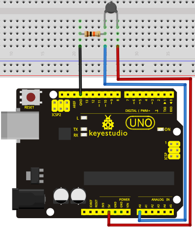
Sample Code: / Örnek Kod
int pin = 7;  //attach to the third pin of NE555
unsigned long duration;  //the variable to store the length of the pulse

void setup()
{
  Serial.begin(9600); //Set serial baud rate to 9600 bps
}
void loop()
{
int val;
val=analogRead(0);//Read rotation sensor value from analog 0
Serial.println(val,DEC);//Print the value to serial port
delay(100);
}
Result:
Shown in pic 1 is data displayed by serial port monitor in room temperature. After the temperature is changed (thermistor wrapped and put into hot water), the data changes as shown in pic 2.
Resim 1'de gösterilen, seri port monitörü tarafından oda sıcaklığında gösterilen verilerdir. Sıcaklık değiştirildikten sonra (termistör sarılıp sıcak suya konur), veriler resim 2'de gösterildiği gibi değişir.
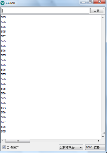
Pic 1
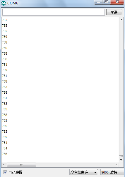
Pic 2
Project 14: LM35 Temperature Sensor / LM35 Sıcaklık Sensörü
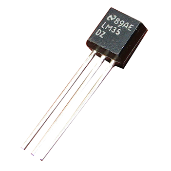
Introduction:
LM35 is a common and easy-to-use temperature sensor. It does not require other hardware. You just need an analog port to make it work. The difficulty lies in compiling the code to convert the analog value it reads to celsius temperature.
LM35, yaygın ve kullanımı kolay bir sıcaklık sensörüdür. Başka bir donanım gerektirmez. Sadece çalışması için bir analog bağlantı noktasına ihtiyacınız var. Zorluk, okuduğu analog değeri santigrat sıcaklığa dönüştürmek için kodun derlenmesinde yatmaktadır. 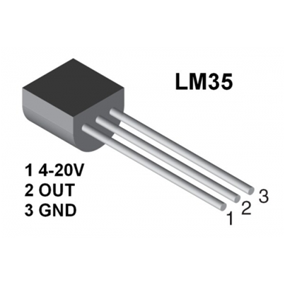
Hardware Required: / Gerekli Donanım
1. Uno R3 board *1
2. USB Cable *1
3. LM35*1
4. Breadboard*1
5. Breadboard jumper wires* several
1. Uno R3 kartı * 1
2. USB Kablosu * 1
3. LM35 * 1
4. Breadboard * 1
5. Breadboard jumper kablo * birkaç adet
Circuit connection: / Bağlantı Şeması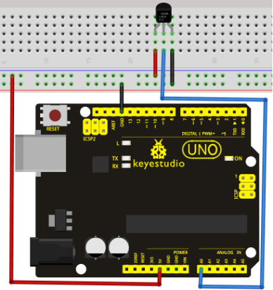
Sample Code: / Örnek Kod
int potPin = 0; // initialize analog pin 0 for LM35 temperature sensor
void setup()
{
Serial.begin(9600);// set baud rate at”9600”
}
void loop()
{
int val;// define variable
int dat;// define variable
val=analogRead(0);// read the analog value of the sensor and assign it to val
dat=(125*val)>>8;// temperature calculation formula
Serial.print("Tep:");// output and display characters beginning with Tep
Serial.print(dat);// output and display value of dat
Serial.println("C");// display "C” characters
delay(500);// wait for 0.5 second
}
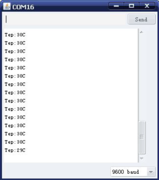
Result: / Sonuç
After downloading the program, you can open the monitoring window to see current temperature.
Programı yükledikten sonra, mevcut sıcaklığı görmek için monitör penceresini açabilirsiniz.
Project 15: A cup with temperature indicator / Sıcaklık Göstergeli Kap
Introduction: / Tanıtım
Now, we will use Arduino to make a temperature-indicated cup. First, let’s design the circuit. When the LM35 temperature sensor senses different temperature, different LED will be turned on representing the temperature.
Şimdi, sıcaklıkla göstergeli bir kap yapmak için Arduino'yu kullanacağız. İlk önce devreyi tasarlayalım. LM35 sıcaklık sensörü farklı sıcaklıklar algıladığında, o sıcaklığı temsil eden farklı bir LED yanacaktır.
Hardware Required: / Gerekli Donanım
1. Uno R3 board *1
2. USB Cable *1
3. Red M5 LED*1
4. Yellow M5 LED*1
5. Blue M5 LED*1
6. 220 ohm Resistor *3
7. LM35 temperature sensor *1
8. Breadboard*1
9. Breadboard jumper wires* several
1. Uno R3 kartı * 1
2. USB Kablosu * 1
3. Kırmızı M5 LED * 1
4. Sarı M5 LED * 1
5. Mavi M5 LED * 1
6. 220 ohm Direnç * 3
7. LM35 sıcaklık sensörü * 1
8. Breadboard * 1
9. Breadboard jumper kablo * birkaç adet
Circuit connection: / Bağlantı Şeması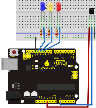
Sample Code: / Örnek Kod
void setup() {
  pinMode(13, OUTPUT);
  pinMode(12, OUTPUT);
  pinMode(11, OUTPUT);
}
void loop() {
  int vol = analogRead(A0) * (5.0 / 1023.0*100);   // read temperature value of LM35
if (vol<=31)                     // low temperature area and LED setup
{
  digitalWrite(13, HIGH);
  digitalWrite(12, LOW);
  digitalWrite(11, LOW);
}
else if (vol>=32 && vol<=40)
 {
   digitalWrite(13, LOW);

  digitalWrite(12, HIGH);
  digitalWrite(11, LOW);
}
else if (vol>=41)                               //  low temperature area and LED setup

{
   digitalWrite(13, LOW);
  digitalWrite(12, LOW);
  digitalWrite(11, HIGH);
}
}
Result: / Sonuç
Corresponding LED will be turned on in accordance with corresponding temperature range.
İlgili sıcaklık aralığına göre ilgili LED yanacaktır.
Project 16: DHT11 Temperature and Humidity Sensor / DHT11 Sıcaklık ve Nem Sensörü
Introduction:
This DHT11 Temperature and Humidity Sensor features calibrated digital signal output with the temperature and humidity sensor complex. Its technology ensures high reliability and excellent long-term stability. A high-performance 8-bit microcontroller is connected. This sensor includes a resistive element and a sense of wet NTC temperature measuring devices. It has excellent quality, fast response, anti-interference ability and high cost performance advantages.
Each DHT11 sensor features extremely accurate calibration data of humidity calibration chamber. The calibration coefficients stored in the OTP program memory, internal sensors detect signals in the process, and we should call these calibration coefficients. The single-wire serial interface system is integrated to make it quick and easy. Qualities of small size, low power, and 20-meter signal transmission distance make it a wide applied application and even the most demanding one. Convenient connection, special packages can be provided according to users need.
Bu DHT11 Sıcaklık ve Nem Sensörü, kalibre edilmiş dijital sinyal çıkışına sahip sıcaklık sensörü ve nem sensörü kompleksinden oluşur. Teknolojisi yüksek güvenilirlik ve mükemmel uzun vadeli istikrar sağlar. Yüksek performanslı bir 8-bit mikrodenetleyici bağlanmıştır. Bu sensör, dirençli bir bileşen ve ıslaklığı hisseden NTC sıcaklık ölçüm cihazları içerir. Mükemmel kalite, hızlı tepki, parazit önleyici özellik ve yüksek fiyat/maliyet performansı avantajlarına sahiptir.
Her DHT11 sensöründe nem kalibrasyon odasının (calibration chamber) son derece hassas kalibrasyon verileri bulunur. Kalibrasyon katsayıları OTP program hafızasında saklanır. Dahili sensörler işlem sırasında sinyalleri algılar ve bu kalibrasyon katsayılarına başvurur. Tek kablolu seri arayüz sistemi, hız ve kolaylık sağlaması için entegre edilmiştir. Küçük ebatı, düşük güç tüketimi ve 20 metrelik sinyal aktarım mesafesi gibi nitelikleri, onu yaygın olarak kullanılan bir uygulama ve hatta en iyisi haline getirir.
Hardware required: / Gerekli Donanım
1. Uno R3 board *1
2. USB Cable *1
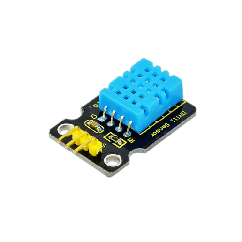
3. Temperature and humidity unit *1
4. 10 Kohm resistor *1
5. Breadboard*1
6. Breadboard jumper wires* several
1. Uno R3 kartı * 1
2. USB Kablosu * 1
3. Sıcaklık ve nem ünitesi * 1
4. 10 Kohm direnci * 1
5. Breadboard * 1
6. Breadboard jumper kablo * birkaç adet
Circuit connection: / Bağlantı Şeması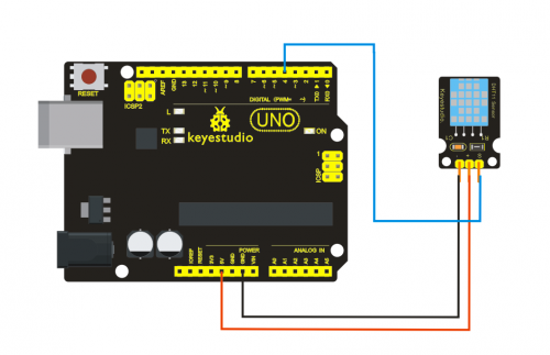
Sample Code :
Please download the DHT11Lib firstly.Or,see the website
Lütfen önce DHT11Lib'i indirin. Veya web sitesine bakın
#includedht11 DHT; #define DHT11_PIN 4 void setup(){ Serial.begin(9600); Serial.println("DHT TEST PROGRAM "); Serial.print("LIBRARY VERSION: "); Serial.println(DHT11LIB_VERSION); Serial.println(); Serial.println("Type,\tstatus,\tHumidity (%),\tTemperature (C)"); } void loop(){ int chk; Serial.print("DHT11, \t"); chk = DHT.read(DHT11_PIN); // READ DATA switch (chk){ case DHTLIB_OK: Serial.print("OK,\t"); break; case DHTLIB_ERROR_CHECKSUM: Serial.print("Checksum error,\t"); break; case DHTLIB_ERROR_TIMEOUT: Serial.print("Time out error,\t"); break; default: Serial.print("Unknown error,\t"); break; } // DISPLAT DATA Serial.print(DHT.humidity,1); Serial.print(",\t"); Serial.println(DHT.temperature,1); delay(1000); }
Result: / Sonuç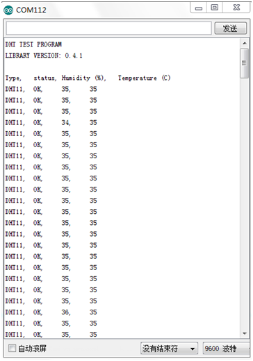
Project 17: Tilt Switch / Eğim Kontağı
Introduction: / Tanıtım
Tilt switch controlling the ON and OFF of LED.
LED'i AÇIK ve KAPALI olarak kontrol eden eğim anahtarı.
Hardware Required: / Gerekli Donanım
1. Uno R3 board *1
2. USB Cable *1
3. Red M5 LED*1
4. Ball switch*1
5. 220 ohm Resistor *1
6. 10 Kohm resistor*1
7. Breadboard*1
8. Breadboard jumper wires* several
1. Uno R3 kartı * 1
2. USB Kablosu * 1
3. Kırmızı M5 LED * 1
4. Top anahtarı * 1
5. 220 ohm Direnç * 1
6. 10 Kohm direnci * 1
7. Breadboard * 1
8. Breadboard jumper kablo * birkaç adet
Circuit connection: / Bağlantı Şeması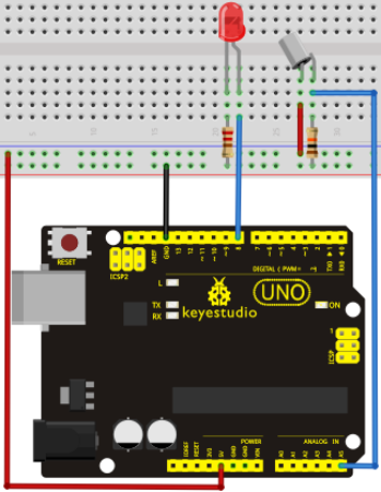
Connect the controller board, shield, breadboard and USB cable according to Arduino tutorial. Connect the LED to digital pin 8, ball switch to analog pin 5.
Denetleyiciyi, shield'i, breadboard'u ve USB kablosunu yukarıdaki görsele göre bağlayın. LED'i dijital pin 8'e, bilyeli anahtarı analog pin 5'e bağlayın.
Experiment Principle: / Deney prensibi
When one end of the switch is below horizontal position, the switch is on. The voltage of the analog port is about 5V (1023 in binary). The LED will be on. When the other end of the switch is below horizontal position, the switch is off. The voltage of the analog port is about 0V (0 in binary). The LED will be off. In the program, we determine whether the switch is on or off according to the voltage value of the analog port, whether it's above 2.5V (512 in binary) or not.
Sample Code: / Örnek Kod
void setup()
{
  pinMode(8,OUTPUT);// set digital pin 8 as "output”
}
void loop()
{
int i;// define variable i
while(1)
{
  i=analogRead(5);// read the voltage value of analog pin 5
  if(i>512)// if larger that 512(2.5V)
  {
    digitalWrite(8,LOW);// turn on LED
  }
  else// otherwise
  {
    digitalWrite(8,HIGH);// turn off LED
  }
 }
}
Result: / Sonuç
Hold the breadboard with your hand. Tilt it to a certain extent, the LED will be on. If there is no tilt, the LED will be off.
The principle of this experiment can be applied to relay control.
Experiment is completed.
Bu deneyin prensibi röle kontrolüne uygulanabilir.
Project 18: Magical Light Cup / Sihirli Işık Kabı
Introduction: / Tanıtım
Magical light cup is a product developed by KEYES that can interact with ARDUINO.
The principle is to use PWM to regulate light brightness of the two components.
Mercury switch provides digital signal, triggering PWM to regulate light brightness. Through the designed program, We can see effect like two cups pouring light to each other.
Magical light cup, Arduino ile etkileşimli, KEYES tarafından geliştirilen bir üründür.
İlkesi, iki bileşenin ışık parlaklığını düzenlemek için PWM kullanmaktır.
Mercury switch, PWM'yi ışık parlaklığını düzenlemek için tetikleyerek dijital sinyal sağlar. Tasarlanan program sayesinde birbirine ışık boşaltan iki bardak gibi bir etki görürüz.
Hardware Required: / Gerekli Donanım
1. Uno R3 board *1
2. USB Cable *1
3. Red M5 LED*2
4. Ball switch*2
5. 220 ohm Resistor *2
6. 10 Kohm resistor*2
7. Breadboard*1
8. Breadboard jumper wires* several
1. Uno R3 kartı * 1
2. USB Kablosu * 1
3. Kırmızı M5 LED * 2
4. Top anahtarı * 2
5. 220 ohm Direnç * 2
6. 10 Kohm direnci * 2
7. Breadboard * 1
8. Breadboard jumper kablo * birkaç adet
Circuit connection: / Bağlantı Şeması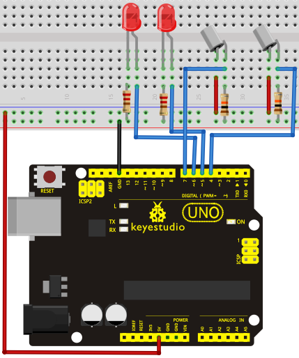
Sample Code: / Örnek Kod
int LedPinA = 5;
int LedPinB = 6;
int ButtonPinA = 7;
int ButtonPinB = 4;
int buttonStateA = 0;
int buttonStateB = 0;
int brightnessA = 0;
int brightnessB= 255;
void setup()
{
Serial.begin(9600);
pinMode(LedPinA, OUTPUT);
pinMode(LedPinB, OUTPUT);
pinMode(ButtonPinA, INPUT);
pinMode(ButtonPinB, INPUT);
}
void loop()
{
buttonStateA = digitalRead(ButtonPinA);
if (buttonStateA == HIGH && brightnessA != 255)
{
brightnessA ++;
}
if (buttonStateA == LOW && brightnessA != 0)
{
brightnessA --;
}
analogWrite(LedPinB, brightnessA);
Serial.print(brightnessA);
Serial.print("   ");
buttonStateB = digitalRead(ButtonPinB);
if (buttonStateB == HIGH && brightnessB != 0)
{
brightnessB --;
}
if (buttonStateB == LOW && brightnessB != 255)
{
brightnessB++;
}
analogWrite(LedPinA, brightnessB);
Serial.println(brightnessB);
delay(5);
}
Result: / Sonuç
Tilt the circuit to one side, A light on, B light out; tilt to the other side, A light out, B light on.
Devreyi bir tarafa eğince, A ışığı yanar, B ışığı söner; diğer tarafa doğru eğince, A ışığı söner, B ışığı yanar.
Project 19: 1-digit LED Segment Display / 1-basamak LED Segment Ekran
Introduction:
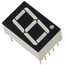
LED segment displays are common for displaying numerical information. It's widely applied on displays of electromagnetic oven, full automatic washing machine, water temperature display, electronic clock etc. It is necessary that we learn how it works.
LED segment display is a semiconductor light-emitting device. Its basic unit is a light-emitting diode (LED). LED segment display can be divided into 7-segment display and 8-segment display according to the number of segments. 8-segment display has one more LED unit ( for decimal point display) than 7-segment one. In this experiment, we use a 8-segment display. According to the wiring method of LED units, LED segment displays can be divided into display with common anode and display with common cathode. Common anode display refers to the one that combine all the anodes of LED units into one common anode (COM).
For the common anode display, connect the common anode (COM) to +5V. When the cathode level of a certain segment is low, the segment is on; when the cathode level of a certain segment is high, the segment is off. For the common cathode display, connect the common cathode (COM) to GND. When the anode level of a certain segment is high, the segment is on; when the anode level of a certain segment is low, the segment is off.
LED segment göstergeleri, sayısal bilgileri görüntülemek için yaygın olarak kullanılır. Yaygın olarak elektromanyetik fırın, tam otomatik çamaşır makinesi, su sıcaklığı göstergesi, elektronik saat vb. göstergelere uygulanır. Nasıl çalıştığını öğrenmemiz gerekir.
LED segment göstergesi yarı iletken ışık yayan bir cihazdır. Temel birimi ışık yayan bir diyottur (LED). LED segment göstergesi, segment sayısına göre 7 segmentli ve 8 segmentli olabilir. 8 segmentli gösterge, 7 segmentli olandan bir fazla LED ünitesine (ondalık nokta gösterimi için) sahiptir. Bu deneyde 8 segmentli bir gösterge kullanıyoruz. LED ünitelerinin kablolama yöntemine göre, LED segment göstergeleri ortak anot göstergesi ve ortak katot göstergesi olarak bölünebilir. Ortak anot göstergesi, LED ünitelerinin tüm anotlarını tek bir ortak anotta (COM) birleştiren gösterge anlamına gelir.
Ortak anot göstergesi için, ortak anotu (COM) +5V'a bağlayın. Belirli bir segmentin katot seviyesi düşük olduğunda, segment açıktır; belirli bir segmentin katot seviyesi yüksek olduğunda, segment kapalıdır. Ortak katot ekranı için ortak katodu (COM) GND'ye bağlayın. Belirli bir segmentin anot seviyesi yüksek olduğunda, segment açıktır; Belirli bir segmentin anot seviyesi düşük olduğunda, segment kapalıdır.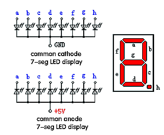
Each segment of the display consists of an LED. So when you use it, you also need to use a current-limiting resistor. Otherwise, LED will be burnt out. In this experiment, we use a common cathode display. As we mentioned above, for common cathode display, connect the common cathode (COM) to GND. When the anode level of a certain segment is high, the segment is on; when the anode level of a certain segment is low, the segment is off.
Ekranın her bölümü bir LED'den oluşur. Bu sebeple kullanırken, akım sınırlayıcı bir direnç de kullanmanız gerekir. Aksi takdirde, LED yanacaktır. Bu deneyde bir ortak katod göstergesi kullanıyoruz. Yukarıda belirttiğimiz gibi, ortak katot gösterimi için, ortak katodu (COM) GND'ye bağlayın. Belirli bir segmentin anot seviyesi yüksek olduğunda, segment açıktır; Belirli bir segmentin anot seviyesi düşük olduğunda, segment kapalıdır.
Hardware Required:
1. Uno R3 board *1
2. USB Cable *1
3. Eight-segment display*1
4. 220 ohm Resistor *2
5. Breadboard*1
6. Breadboard jumper wires* several
1. Uno R3 kartı * 1
2. USB Kablosu * 1
3. Sekiz segmentli ekran * 1
4. 220 ohm Direnç * 2
5. Breadboard * 1
6. Breadboard jumper kablo * birkaç adet
Circuit connection: / Bağlantı Şeması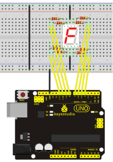
Sample Code: / Örnek Kod
There are seven segments for numerical display, one for decimal point display. Corresponding segments will be turned on when displaying certain numbers. For example, when displaying number 1, b and c segments will be turned on. We compile a subprogram for each number, and compile the main program to display one number every 2 seconds, cycling display number 0 ~ 9. The displaying time for each number is subject to the delay time, the longer the delay time, the longer the displaying time.
Sayısal gösterim için yedi, ondalık gösterim için bir segment bulunur. Belli sayıları görüntülerken ilgili segmentler açılacaktır. Örneğin, 1 sayısını görüntülerken, b ve c segmentleri açılacaktır. Her sayı için bir alt program derliyoruz ve ana programı 0'dan 9'a kadar olan sayıları her 2 saniyede bir sayı gösterecek şekilde derliyoruz. Her sayının ne kadar süre görüntüleneceği, "delay ()" (uzama) süresine bağladır ve ne kadar uzunsa, gösterim süresi o kadar uzun olur.
// set the IO pin for each segment
int a=7;// set digital pin 7 for segment a
int b=6;// set digital pin 6 for segment b
int c=5;// set digital pin 5 for segment c
int d=10;// set digital pin 10 for segment d
int e=11;// set digital pin 11 for segment e
int f=8;// set digital pin 8 for segment f
int g=9;// set digital pin 9 for segment g
int dp=4;// set digital pin 4 for segment dp
void digital_0(void) // display number 5
{
unsigned char j;
digitalWrite(a,HIGH);
digitalWrite(b,HIGH);
digitalWrite(c,HIGH);
digitalWrite(d,HIGH);
digitalWrite(e,HIGH);
digitalWrite(f,HIGH);
digitalWrite(g,LOW);
digitalWrite(dp,LOW);
}
void digital_1(void) // display number 1
{
unsigned char j;
digitalWrite(c,HIGH);// set level as "high” for pin 5, turn on segment c
digitalWrite(b,HIGH);// turn on segment b
for(j=7;j<=11;j++)// turn off other segments
digitalWrite(j,LOW);
digitalWrite(dp,LOW);// turn off segment dp
}
void digital_2(void) // display number 2
{
unsigned char j;
digitalWrite(b,HIGH);
digitalWrite(a,HIGH);
for(j=9;j<=11;j++)
digitalWrite(j,HIGH);
digitalWrite(dp,LOW);
digitalWrite(c,LOW);
digitalWrite(f,LOW);
}
void digital_3(void) // display number 3
{digitalWrite(g,HIGH);
digitalWrite(a,HIGH);
digitalWrite(b,HIGH);
digitalWrite(c,HIGH);
digitalWrite(d,HIGH);
digitalWrite(dp,LOW);
digitalWrite(f,LOW);
digitalWrite(e,LOW);
}
void digital_4(void) // display number 4
{digitalWrite(c,HIGH);
digitalWrite(b,HIGH);
digitalWrite(f,HIGH);
digitalWrite(g,HIGH);
digitalWrite(dp,LOW);
digitalWrite(a,LOW);
digitalWrite(e,LOW);
digitalWrite(d,LOW);
}
void digital_5(void) // display number 5
{
unsigned char j;
digitalWrite(a,HIGH);
digitalWrite(b, LOW);
digitalWrite(c,HIGH);
digitalWrite(d,HIGH);
digitalWrite(e, LOW);
digitalWrite(f,HIGH);
digitalWrite(g,HIGH);
digitalWrite(dp,LOW);
}
void digital_6(void) // display number 6
{
unsigned char j;
for(j=7;j<=11;j++)
digitalWrite(j,HIGH);
digitalWrite(c,HIGH);
digitalWrite(dp,LOW);
digitalWrite(b,LOW);
}
void digital_7(void) // display number 7
{
unsigned char j;
for(j=5;j<=7;j++)
digitalWrite(j,HIGH);
digitalWrite(dp,LOW);
for(j=8;j<=11;j++)
digitalWrite(j,LOW);
}
void digital_8(void) // display number 8
{
unsigned char j;
for(j=5;j<=11;j++)
digitalWrite(j,HIGH);
digitalWrite(dp,LOW);
}
void digital_9(void) // display number 5
{
unsigned char j;
digitalWrite(a,HIGH);
digitalWrite(b,HIGH);
digitalWrite(c,HIGH);
digitalWrite(d,HIGH);
digitalWrite(e, LOW);
digitalWrite(f,HIGH);
digitalWrite(g,HIGH);
digitalWrite(dp,LOW);
}
void setup()
{
int i;// set variable
for(i=4;i<=11;i++)
pinMode(i,OUTPUT);// set pin 4-11as "output”
}
void loop()
{
while(1)
{
digital_0();// display number 0
delay(1000);// wait for 1s
digital_1();// display number 1
delay(1000);// wait for 1s
digital_2();// display number 2
delay(1000); // wait for 1s
digital_3();// display number 3
delay(1000); // wait for 1s
digital_4();// display number 4
delay(1000); // wait for 1s
digital_5();// display number 5
delay(1000); // wait for 1s
digital_6();// display number 6
delay(1000); // wait for 1s
digital_7();// display number 7
delay(1000); // wait for 1s
digital_8();// display number 8
delay(1000); // wait for 1s
digital_9();// display number 9
delay(1000); // wait for 1s
}
}
Result: / Sonuç
LED segment display displays number 0 to 9
LED segment göstergesi, 0 ~ 9 arasındaki sayıları gösterecektir.
Resources / Kaynaklar
Video
http://www.keyestudio.com/wp/ks0070/
https://drive.google.com/open?id=1r2srrIHZjc-AXSXRVqDMpbdA30MIkJsd